Chapter 2 Locations and Functions of Parts
2-4(E) Chapter 2 Locations and Functions of Parts
2-2 Controls and Connectors
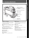
Front (Left)
5 VF connector
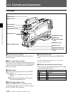
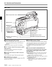
1 TEST OUT (test output) connector (BNC type)
Connect to a monitor to as necessary. The output will
be the signal selected with the Y/RGB and R/G/B/
switches.
2 MIC 1 IN (microphone 1 input) connector (XLR
3-pin, female)
Connect a microphone.
This connector and the AUDIO IN CH-1 connector on
the back are alternately activated with the MIC IN
switch.
3 RET 1 (return video 1) button
The return video 1 signal from the camera control unit
is monitored on the viewfinder screen while this button
is pressed. It is the same function as with the RET 1
buttons on the grip and right side.
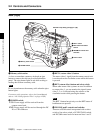
6 SHUTTER switch
7 INCOM/EAR LEVEL control
8 VTR START button
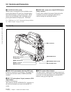
3 RET 1 connector
4 MIC IN switch
1 TEST OUT connector
For future use
2 MIC 1 IN connector
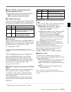
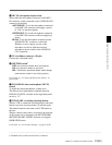
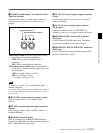
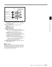
qd CANCEL/STATUS switch
When a menu is displayed on the viewfinder screen,
pressing this button will cancel any changed setting
and return the display to the previous menu. When
menus are not displayed on the viewfinder screen,
pressing this button will display the ‘!’IND item.
For ‘!’IND items, see “4-6-2 Selecting the Items for Which
an ‘!’ Mark to Light” on page 4-17(E).
qf MENU SEL (menu select) knob/ENTER button
(rotary encoder)
Used to select settings from menus displayed on the
viewfinder screen (by rotating the knob) and to
confirm settings (by pushing the button).


