


Chapter 2 Locations and Functions of Parts
2-6(E) Chapter 2 Locations and Functions of Parts
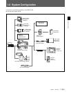
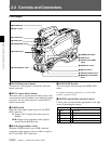
2-2 Controls and Connectors
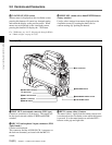
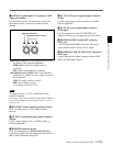
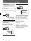
1 TALLY lamp and TALLY switch
ON: The tally lamp lights when a tally signal or a call
signal generated by pressing a CALL button is
received.
OFF: The tally lamp is prevented from lighting.
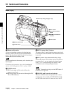
2 CCU (Camera Control Unit) connector (optical
multi connector)
Connects to a camera control unit via an optical
electro-composite cable.
3 INCOM1 and 2 (intercom 1 and 2) connectors
(XLR 5-pin)
Used for input and output of intercom audio signals.
4 EARPHONE jack (minijack)
Connect an earphone or headset for output of the VTR
playback audio signal.
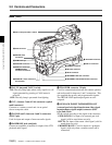
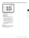
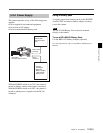
Back (Left)
0 REMOTE connector
5 TRACKER connector (20-pin)
Used for communication between the camera operator
and tracker and for intercom 1 and 2 connection. This
also supplied the up tally and program audio signals.
The TRUNK LINE input/output signals are also
assigned.
6 GENLOCK IN/RET IN/PROMPTER OUT
(external gen-lock signal input/return video signal
input/prompter signal output) connector (BNC
type) and switch
Set the switch according to the signal at the connector.
GENLOCK IN: For input of an external gen-lock
signal (valid in stand-alone use only)
RET IN: For input of the return video signal (valid in
stand-alone use only)
PROMPTER OUT: Used for output of a prompter
signal (valid only when a camera control unit is
connected)
qa DC OUT connector
qs DC IN connector
qd HD SERIAL RET OUT connector
qf HD SERIAL LINK A/LINK B OUT connectors
1 TALLY lamp and TALLY switch
2 CCU connector
3 INCOM1 and 2
connectors
4 EARPHONE jack
5 TRACKER connector
6 GENLOCK IN/RET IN/
PROMPTER OUT
connector and switch
7 AUDIO IN 1 and 2 connectors
and switches
8 RET CONT connector
9 EXT I/O connector