


Chapter 2 Locations and Functions of Parts
2-2(E) Chapter 2 Locations and Functions of Parts
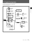
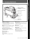
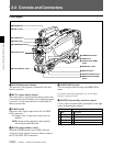
2-2 Controls and Connectors
2-2 Controls and Connectors
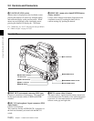
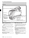
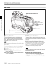
Front (Right)
8 CAMERA/VTR switch
9 GAIN switch
0 OUTPUT/AUTO KNEE
switch
qa WHITE BAL switch
1 INCOM (intercom 1) button
The intercom 1 microphone is turned ON while this
button is pressed.
2 RET 1 (return video 1) button
The return video 1 signal from the camera control unit
is monitored on the viewfinder screen while this button
is pressed. It is the same function as with the RET 1
buttons on the sides.
3 Y/RGB switch
Select the video signal output for the VF and TEST
OUT connectors.
Y: Output is the Y signal (this is the power-on
default).
RGB: Output is the component video signal(s)
selected by the R/G/B switch.
4 R/G/B (red/green/blue) switch
When the Y/RGB switch is set to RGB, select the
component video signal(s) to be provided as output to
the VF and TEST OUT connectors.
5 ASSIGNABLE switch
You can assign a function using the OPERATION
menu.
For details on function assignment, see “4-6-8 Other
Settings” on page 4-21(E).
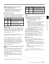
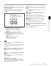
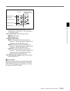
6 FILTER (internal filter selection) control
Used to select an internal filter appropriate for the light
source illuminating the subject.
ND Filter
Color temperature conversion filter
1 clear A cross filter
2 1/4 ND B 3200K
3 1/8 ND C 4300K
4 1/16 ND D 6300 K
5 1/64 ND E 8400 K
qs DISPLAY switch
qd CANCEL/STATUS switch
qf MENU SEL knob/ENTER
button
3 Y/RGB switch
4 R/G/B switch
5 ASSIGNABLE switch
6 FILTER control
7 AUTO W/B BAL switch
1 INCOM button
2 RET 1 button