


21
Location and Function of Parts
Chapter 1 Overview
WRR-855 series UHF synthesized tuner (supplied
separately) is installed using the CA-WR855
R (REAR): Audio input signals from an audio device
connected to the AUDIO IN CH-1/CH-2 connectors
(The signal input to the AUDIO IN CH-1 connector is
recorded on channel 3, and the signal input to the
AUDIO IN CH-2 connector on channel 4.)
For audio channels 3 and 4, level adjustment can only be
performed in AUTO (automatic) mode. The audio level of
these channels cannot be adjusted in MANUAL (manual)
mode.
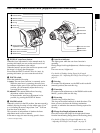
k VIDEO OUT (video output) CHARACTER switch
Selects whether or not (ON/OFF) to superimpose text
information on the VIDEO OUT connector output.
l F-RUN/SET/R-RUN (free run/set/recording run)
switch
Selects the operating mode of the internal timecode
generator. The operating mode is set as explained below,
depending on the position of the switch.
F-RUN: Timecode keeps advancing, regardless of the
operating state of the VDR. Use this setting when
synchronizing the timecode with an external
timecode.
SET: Sets the timecode or user bits.
R-RUN: Timecode advances only during recording. Use
this setting to have a consecutive timecode on the
disc.
For details, see “To set the timecode” on page 61 and “To
set the user bits” on page 62.
m FRONT MIC LOW CUT switch
Set to ON to insert a high-pass filter in the microphone
circuit, reducing wind noise. Normally leave the switch in
the OFF position.
n PRESET/REGEN (regeneration)/CLOCK switch
Selects whether to set a new timecode or to utilize the
existing timecode.
PRESET: Records a new timecode.
REGEN: Records timecode continuous with the existing
timecode recorded on the disc. Regardless of the
setting of the F-RUN/SET/R-RUN switch, the
camcorder operates in R-RUN mode.
CLOCK: Records timecode synchronized to the internal
clock. Regardless of the setting of the F-RUN/SET/R-
RUN switch, the camcorder operates in F-RUN mode.
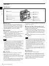
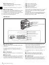
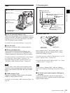
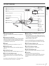
Left Side and Upper Section
a ASSIGN 3/4 switches
You can assign the desired functions to these switches on
the ASSIGNABLE page of the OPERATION menu.
For details, see “Assigning Functions to ASSIGN
Switches” on page 141.
b Large viewfinder attachment shoe
Use this to mount an optional 5-inch electronic viewfinder
(see page 38).
Note
1 ASSIGN 3/4 switches
2 Large viewfinder attachment shoe
4 Lid of the disc compartment
6 Shoulder strap fitting
7 Viewfinder left-to-right positioning ring
8 Viewfinder fitting shoe
qa MIC IN connector
9 Fitting for optional microphone holder
0 LIGHT connector
3 Viewfinder front-to-back
positioning knob
5 Accessory fitting shoe
qs Shoulder pad
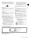
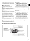
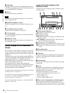
1Video output and timecode connectors
(see page 22)