


24
Location and Function of Parts
Chapter 1 Overview
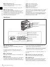
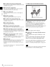
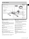
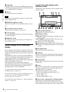
c AUDIO IN CH-1/CH-2 (audio input channel 1/2)
connectors (XLR type, 3-pin, female) and input
selection switches
Connect other audio equipment or external microphone.
Set the input selection switches as shown below according
to the microphone or equipment.
LINE (left position): For connecting an external audio
signal source such as a stereo amplifier
MIC (center position): For connecting any microphone
other than 48 V microphone
MIC +48V ON (right position): For connecting a 48 V
microphone
Signals input to the AUDIO IN CH-1 connector can be
recorded on audio channels 1 and 3. Similarly, signals
input to the AUDIO IN CH-2 connector can be recorded on
audio channels 2 and 4.
1)
1) When the AUDIO IN (CH-1/CH-2/CH-3/CH-4) switches on the side
control panel are set to “REAR” or “R”.
If MIC +48V ON is selected for a microphone other than
48 V microphone, the microphone may be damaged.
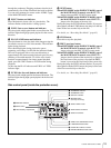
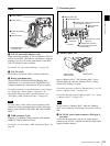
d (i.LINK) DV OUT S400 connector (6-pin, IEEE
1394 compliant)
Connect to a device supporting the DV format or a
computer, using an i.LINK cable (DV cable).
• If video and audio signals are not output from the
external device connected to the (i.LINK) DV OUT
S400 connector, disconnect the i.LINK cable (DV cable)
and then reconnect it, making sure that it is firmly seated.
• When you connect the camcorder and other equipment,
such as a hard disk drive, with an i.LINK interface to a
computer with i.LINK connectors, turn off the power of
the computer, the other equipment, and the camcorder
before connecting them using the i.LINK cable (DV
cable). If a bus-powered type
1)
hard disk drive or similar
equipment is connected while the computer is powered
on, electric current flows into the camcorder because of
the high voltage caused by the load shift of the computer
power, and this may cause a malfunction.
1) Equipment that can be powered through i.LINK cable (DV cable)
e REMOTE connector (8-pin)
Connect an RM-B150/B750 Remote Control Unit, which
makes it possible to control the camcorder remotely.
Before connecting/disconnecting the Remote Control Unit
to/from the camcorder, be sure to turn off the camcorder
POWER switch.
f DC OUT 12V (DC power output) connector (4-pin,
female)
Supplies power for a WRR-861/862 UHF Synthesized
Tuner (optional) (maximum 0.2 A).
Do not connect any equipment other than the UHF
synthesized tuner.
g TC (timecode) connector (BNC type) and IN/OUT
selector switch
• IN/OUT selector switch: IN
To apply an external lock to the timecode, input the
reference timecode.
• IN/OUT selector switch: OUT
To lock the timecode of an external VTR to the timecode
of this unit, connect this connector to the external VTR’s
timecode input connector.
h VIDEO OUT (video output) connector (BNC type)
Outputs a video signal for a video monitor. When the
output signal is composite, setting menus, timecode, or
shot data can be superimposed on the camera output video
depending on the menu settings, and you can view them on
the monitor screen. To lock the timecode of an external
device to the timecode of this unit, connect the genlock
signal input connector of the external device to this
connector.
• The subcarrier phsase cannot be adjusted.
• Video signals are not output if the connection
destinations of these connectors are not terminated
properly.
i AUDIO OUT CH-1/CH-2 (audio output channel 1/
2) connectors (phono jacks)
Output the audio singnals being recorded or played back.
Connect to a stereo amplifier or video monitor’s audio
input connectors.
Note
Notes
Note
Notes