


23
Location and Function of Parts
Chapter 1 Overview
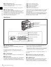
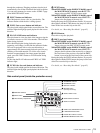
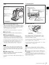
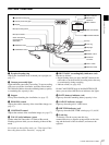
Rear
a TALLY (back tally) indicator (red)
Lights up during recording. It will not light if the TALLY
switch is set to OFF. This indicator also flashes to indicate
warnings (see page 18) in the same manner as the REC/
TALLY indicator in the viewfinder.
For details, see “Operation Warnings” on page 165.
b TALLY switch
Set to ON to activate the TALLY indicator function.
c Battery attachment shoe
Attach a BP-GL95/GL65/L60S/L80S Battery Pack.
Alternatively, you can attach an AC-DN2B/DN10 AC
Adaptor to operate the camcorder on AC power supply.
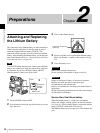
For details about how to attach the battery or AC adaptor,
see “Preparing a Power Supply” on page 31. For
information about attaching a synthesized tuner, see
“Attaching a UHF Synthesized Tuner” on page 42.
For your safety, and to ensure proper operation of the
camcorder, Sony recommends the use of the following
battery packs: BP-GL95, BP-GL65, BP-L60S, and BP-
L80S.
d WRR connector (7-pin)
Connect a CA-WR855 Camera Adaptor with attached
WRR-855 UHF Synthesized Tuner.
For details, see “Attaching a UHF Synthesized Tuner” on
page 42.
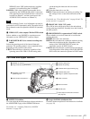
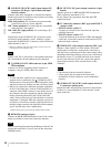
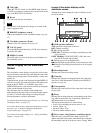
1 Connector panel
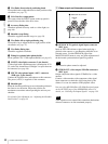
a “Memory Stick” slot
Insert a “Memory Stick”. The “Memory Stick” access
indicator lights up when the “Memory Stick” is being
accessed for reading or writing.
For details about how to insert a “Memory Stick”, see “To
insert a “Memory Stick”” on page 145.
For details about the types of “Memory Stick”, see “About
a “Memory Stick”” on page 174.
Do not remove a “Memory Stick” while the “Memory
Stick” access indicator is lit. Doing so may cause a loss of
data.
b DC IN (DC power input) connector (XLR type, 4-
pin, male)
To operate the camcorder using an AC power supply,
connect an AC-550 AC Adaptor with the DC output cable
supplied with the adaptor.
Note
1 TALLY indicator
2 TALLY switch
3 Battery attachment
shoe
4 WRR connector
1 Connector panel
(see page 23)
Note
1 ”Memory Stick” slot
2 DC IN connector
3 AUDIO IN CH-1/CH-2 connectors and
input selection switches
5 REMOTE
connector
6 DC OUT 12V
connector
7 TC connector and IN/OUT
selector switch
8 VIDEO OUT connector
9 AUDIO OUT CH-1/CH-2
connectors
4 DV OUT S400
connector
“Memory Stick”
access indicator
“Memory Stick”