


27
E. TRG (External trigger)7. 4
Charge begins to accumulate after the trigger input to CC1 of the DIGITAL terminal, and 1 frame images are output.
There are four modes: 1P SNR, 1P SR, PW SNR, PW SR.
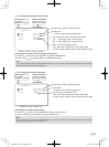
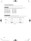
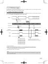
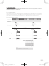
1P SNR (1 Pulse Trigger Sync Non Reset)( 1 )
Charge begins to accumulate after the trigger input to CC1 of the DIGITAL terminal, and 1 frame images are output.
1 Pulse Trigger SYNC-NON RESET Picture Output Timing(1. 1)
About 1 µs
External VD IN*
1
External HD IN*
1
(Internal VD)
Trigger*
1
About 1H
Negative polarity mode
Positive polarity mode
Exposure period*
2
Exposure period*
2
RGB data
(video interval image)
FVAL
LVAL,
DVAL
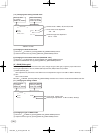
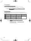
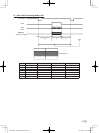
28H Partial scanning OFF
25H Partial scanning 40fps
27H Partial scanning 42fps
33H Partial scanning 50fps
39H Partial scanning 60fps
43H Partial scanning 70fps
46H Partial scanning 80fps
48H Partial scanning 90fps
The internal VD falling edge is within the
exposure period and thus video is not output. *
3
*
4
*1: External input signal
*2: Exposure time is determined by the setting of “7. 2 (1.3) Changing the setting in E.TRG mode”.
*3: Video is output at the falling edge of the internal VD following completion of the exposure period.
The video and FVAL/LVAL/DVAL have a paired relationship.
*4: When NR is set to ON, 1H is increased.
Note:
When the next trigger is input before completion of the output of the video corresponding to the trigger, there
will be an effect on the video.
120730c1_IK_TF7P2_EN.indd 27 12.7.30 1:19:03 PM