


35
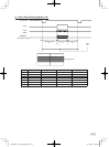
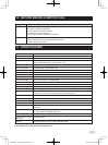
INPUT OUTPUT SIGNAL SPECIFICATIONS8.
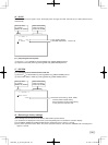
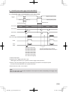
(1)HDInputSpecications (2)VDInputSpecications
2.0µs 5.0µs
5H 21H
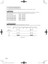
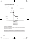
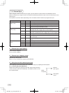
( 3 ) Trigger Pulse Specifications
(Positive polarity mode)
(Negative polarity mode)
More than 2 µs
More than 2 µs
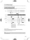
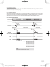
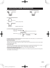
(4)ExternalHD/VDInputPhaseSpecications
100 100
External VD
falling edge
Center
Unit : Clock
1 clk=33.9ns
External HD
The phase relationship of the external HD and VD should correspond to the center phase (i.e., the external HD fall-
ing edge) as illustrated in the above diagram.
ExternalVDfallingedge:
Please input within about 100 clock cycles of the standard center phase.
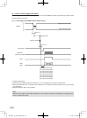
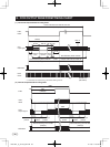
Note that V sync of the video is output with a delay of about 2H from the external VD at the time of reset-restart
and the external trigger mode.
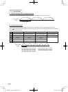
In the normal mode:
Continuously with the HD period of 43.05 μs and VD period of 34.27 ms (partial scanning 40fps: 24.97 ms, 42fps:
23.81 ms, 50fps: 20.02 ms, 60fps: 16.66 ms, 70fps: 14.29ms, 80fps: 12.49 ms, 90fps: 11.11 ms).
Phase timing is as illustrated in the above diagram (with only the falling edge applicable).
In the reset-restart/external trigger mode:
Continuously with the HD period of 43.05 μs. VD (reset) is at an arbitrary timing with the phase of HD being within
the standard of the above diagram.
120730c1_IK_TF7P2_EN.indd 35 12.7.30 1:19:05 PM