


7
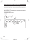
CONNECTION4.
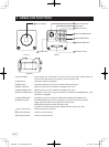
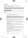
Standard Connection4. 1
IK-TF7P2
DC IN 12V
Lens
Cable (not included)
Frame grabber board,
image process
equipment etc.
Monitor
DC power
supply
Less than 4 mm
Cautions on Connection4. 2
• When connecting the camera cables, be sure to unplug the power source of the camera and the other equip-
ment connected to it.
• We suggest using a C mount lens made for a 3CCD color camera.
When using another lens, the best camera performance of this camera may not be obtained.
(For example, low resolution may occur, focus may be lost through the range of a zoom lens, and flare, ghost
or shading may occur)
Furthermore, in order to avoid damaging the mounting portion of the camera head, use a lens which has
projection dimension from the mounting base of less than 0.157”(4mm).
• The camera may be powered in two ways:
(1) Supplied to the DC IN 12V terminal
• For DC power supply connecting to DC IN 12V terminal, use UL listed and/or CSA approved unground-
ing type AC adaptor with the specifications described below.
Power supply voltage : DC12V±10%
Current rating : More than 830 mA
Ripple voltage : Less than 50 mV(p–p)
Connector : HR10A–7P–4S by HIROSE electronics Co. Ltd
Pins 1, 2 : 12V
Pins 3, 4 : GND
• For DC power supply connecting to DC IN 12V terminal, use class II DC power supply approved accord-
ing to EN60950-1 in Europe.
(2) Supplied to the DIGITAL terminal
• Supply the DC power supply (DC10V-DC13V) to pins 1 and 26 of the cable (sold separately).
• When using PoCL (power over camera link) to power the camera, use a standard PoCL cable.
* Use only one power supply type at a time.
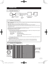
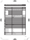
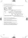
Connector Pin Assignments4. 3
DC IN 12V DIGITAL Function I/O
1 +12V 1 +12V 14 GND –
2 +12V 2 X0- 15 X0+ O
113
26
14
Connector used:
12226-51000-00
(3M) or equivalent.
3 GND 3 X1- 16 X1+ O
4 GND 4 X2- 17 X2+ O
Connector used:
HR10A-7P-4PB
(HIROSE electronics
Co. Ltd) or equivalent.
1
2
3
4
5 Xclk- 18 Xclk+ O
6 X3- 19 X3+ O
7 SerTC+ 20 SerTC- Serial communication control (RXD) I
8 SerTFG- 21 SerTFG+ Serial communication control (TXD) O
9 CC1- 22 CC1+ Trigger pulse input I
10 CC2+ 23 CC2- Partial scanning control I
11 CC3- 24 CC3+ External HD input I
12 CC4+ 25 CC4- External VD input I
13 GND 26 +12V –
120730c1_IK_TF7P2_EN.indd 7 12.7.30 1:18:59 PM