


4
Limitation of Usage
The product is not designed for any “critical applications.” “Critical applications” means life support
systems, exhaust or smoke extraction applications, medical applications, commercial aviation,
mass transit applications, military applications, homeland security applications, nuclear facilities or
systems or any other applications where product failure could lead to injury to persons or less of life
or catastrophic property damage. Accordingly, [Toshiba/TAIS] disclaims any and all liability arising
out of the use of the product in any critical applications.
TABLE OF CONTENTS
1. CAUTIONS ON USE AND INSTALLATION .....5
2. COMPONENTS ................................................5
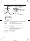
3. NAMES AND FUNCTIONS ..............................6
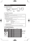
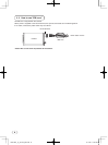
4. CONNECTION ..................................................7
4. 1 Standard Connection ................................7
4. 2 Cautions on Connection ............................7
4. 3 Connector Pin Assignments ......................7
4. 4 How to use “EMI core” ..............................8
5. OPERATION .....................................................9
5. 1 White Balance ........................................... 9
5. 2 Gain ........................................................10
5. 3 Shading Correction .................................10
6. ITEMS CONTROLLED BY THE SCREEN
DISPLAY ......................................................... 11
7.
MODE SETTING BY ON SCREEN DISPLAY
.... 12
7. 1 Using the Menus .....................................12
7. 2 Menus .....................................................13
( 1 ) SHUTTER (Electronic shutter) ................ 13
(1. 1) Changing the setting in
MANU mode.................................14
(1. 2) Changing the setting in
SS (synchro. scan) mode .............15
(1. 3) Changing the setting in
E.TRG mode ................................16
(1. 3. 1) Changing the setting in
1P SNR mode ........................... 16
(1. 3. 2) Changing the setting in
1P SR mode .............................17
(1. 3. 3) Changing the setting in
PW SNR mode .........................18
(1. 3. 4) Changing the setting in
PW SR mode ............................19
(1. 3. 5) Changing the setting in
RR mode...................................19
(1. 4) Changing each setting in
AUTO mode .................................20
( 2 ) GAIN (Video gain) ................................... 20
(2. 1) Changing the setting in GAIN.......20
( 3 ) WHT BAL (White balance) ...................... 21
(3. 1)
Changing the setting in AWB
(Automatic White Balance) mode
... 21
(3. 2) Changing the setting in MANU
(Manual) mode .............................21
( 4 ) PROCESS ..............................................22
(4. 1) Changing gamma correction ........ 22
(4. 2) Changing master pedestal ...........22
(4. 3) Changing R pedestal ...................22
(4. 4) Changing B pedestal ....................22
(4. 5) Changing noise reduction ............22
( 5 ) SHADING ................................................23
(5. 1)
Changing V.SHAD. (Vertical Shading)
correction mode ...........................24
(5. 2)
Changing the manual V.SHAD. (Vertical
Shading) correction setting
.............24
(5. 3)
Changing C.SHAD. (Corner Shading)
correction mode ...........................24
(5. 4)
Changing the manual C.SHAD. (Corner
Shading) correction setting ............24
( 6 ) SYNC ......................................................25
(6. 1) Adjusting horizontal phase ........... 25
( 7 ) OPTION ..................................................25
(7. 1) Changing serial communication
baud rate ......................................25
( 8 ) Returning to factory settings ...................25
7. 3 Synchro. Scan Operation ........................26
( 1 ) Setting by 1H ..........................................26
( 2 ) Setting by the frame ................................26
7. 4 E. TRG (External trigger) ........................27
( 1 ) 1P SNR (1 Pulse Trigger
Sync Non Reset) ..................................... 27
(1. 1) 1 Pulse Trigger SYNC-NON
RESET Picture Output Timing .....27
( 2 ) 1P SR (1 Pulse Trigger Sync Reset) ....... 28
(2. 1) 1 Pulse Trigger SYNC-RESET
Picture Output Timing ..................28
( 3 ) PW SNR (Pulse width trigger
SYNC-NON RESET) ...............................29
(3. 1) Pulse Width Trigger SYNC-NON
RESET Picture Output Timing .....29
( 4 ) PW SR (Pulse width trigger
SYNC-RESET) ........................................30
(4. 1) 1 Pulse Width Trigger SYNC-RESET
Picture
Output Timing ..................30
( 5 ) RR (Reset restart) ...................................31
(5. 1) Long Term Exposure ....................31
(5. 2) Input Timing Chart Example.........31
120730c1_IK_TF7P2_EN.indd 4 12.7.30 1:18:59 PM