


TV-IP612P/WN (Wireless N) Pan/Tilt/Zoom Internet Camera
49
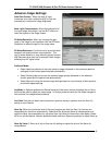
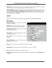
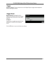
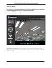
Patrol Selection: This box shows the available Preset Locations saved which can be moved to the
Selected Locations box below by highlighting them and clicking on the Select button.
Selected Locations: The preset locations in this box: determine the locations the camera will view
when the Patrol button is pressed in the Live View window.
Pan/Patrol Speed: Set the speed from 1 to 5 with 5 being the fastest. This controls the speed of
the camera movements when either the Pan or Patrol button is pressed in the Live View page.
Dwelling Time: The setting here determines how long the camera spends at the preset position.
Enter from 1 to XXXX seconds.
Click the Save button to save and activate your settings.
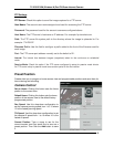
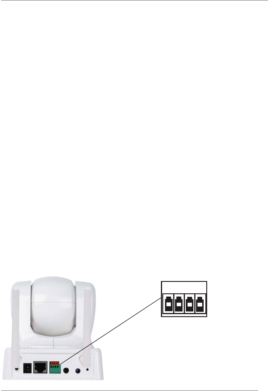
Digital Output
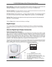
The camera’s Digital I/O terminal block is the physical connection or interface for connecting
external devices suchs as InfraRed Sensors, Alarm Relays, and Srents to the TV-IP612P/WN
camera.
External Digital Input/Output Connectors
Digital I/O Terminal Block Description
The TV-IP612P/WN camera is equipped with a Input/Output termincal block that provides a single
digital input and a relay to control external devices. Using Pins 1 and 2 allows you to connect a
devices such as an external sensor (e.g. IR Sensor or Alarm Relays) so that the camera can
monitor the voltage state where the initial state is set to “LOW” or deactivated. Pin 3 and 4 are
connected to the camera’s output relay so that an external device can be controlled with “HIGH”
activate or “LOW” deactivate signals (e.g. an external circuit to operate a Siren).
Using the I/O terminal block allows you to connect multiple external alarm devices that can then be
used to trigger image recording or snapshots that can be stored or emailed to a remote location.
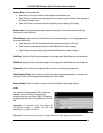
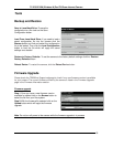
Below is the diagram of the terminal block with the connector pin descriptions.
4
3
2
1
Input Output (I/O) Connector
PIN Description
1 DI + INPUT (Maximum 50mA & 12VDC)
2 DI - INPUT (DI is initially set to low state)
3 SW_COMMON OUTPUT (Initial state is SW_OPEN)
(SW_OPEN is closed when DO is HIGH)
4 SW_NOPEN OUTPUT (Maximum 1A & 24VDC or
0.5A &125VAC)