


AXIS 2100 User’s Guide Physical Description
9
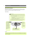
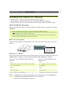
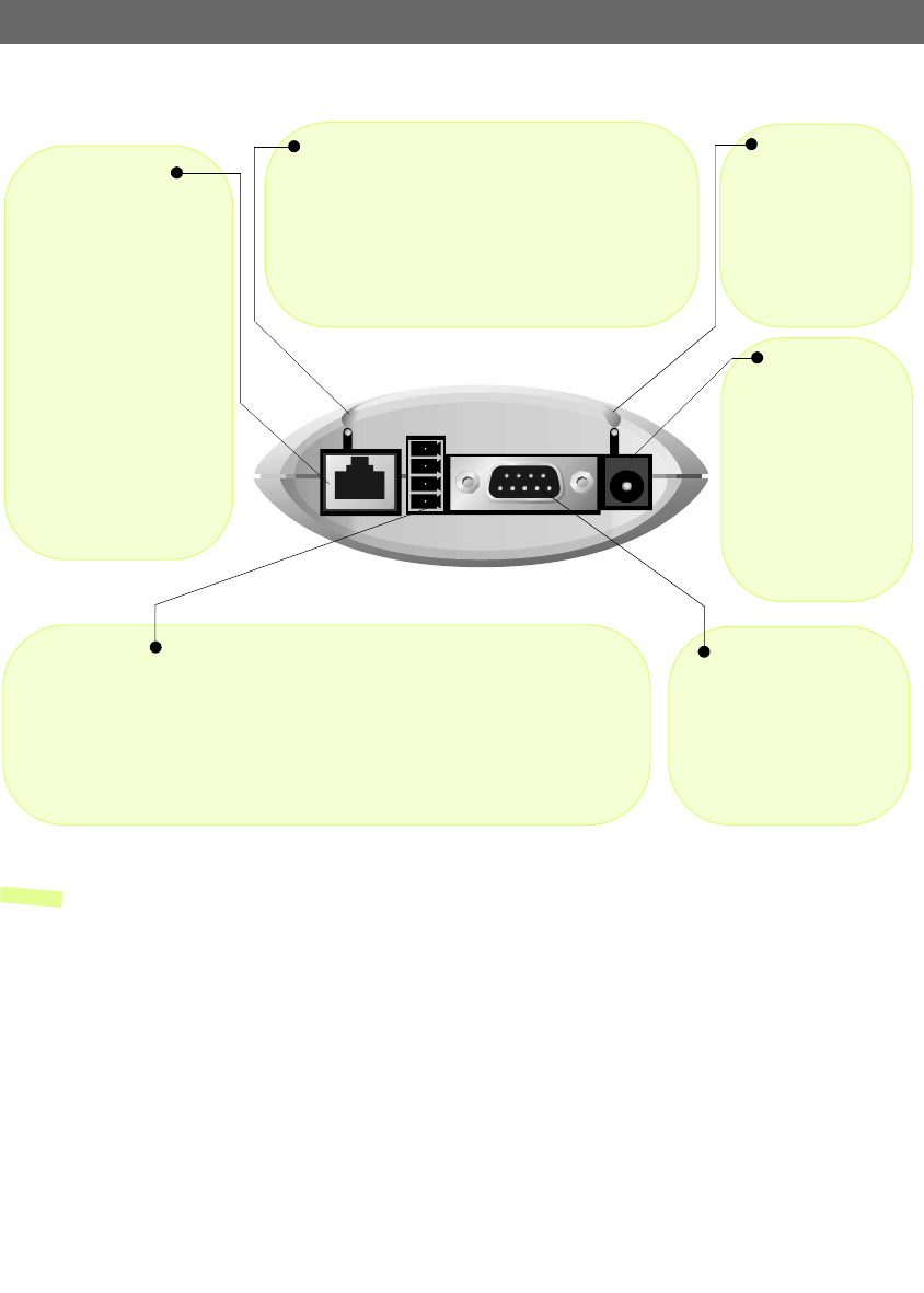
Rear Panel
Note: The power supply supplied with your AXIS 2100 is country specific. Please check that the type of
power supply you are using is correct. See page 10.
Power Supply
Connector
A single Jack socket
(PS-D) for connection
of AXIS 2100 power
supply. The terminal
block connector pro-
vides an auxiliary con-
nection point for AC
or DC power to the
unit.
Power Indicator
Normally lit when
power is applied. If it
is not lit, or it flashes,
there is a problem
with the AXIS 2100
external power
source.
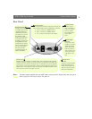
Network Indicator
After completion of the startup and self test routines, this
multi-colored indicator flashes independently, as follows:
• yellow - activity on a 10Mbps network
• green - activity on a 100Mbps network
• red - no physical connection to the network
Network Connector
The AXIS 2100 is designed
for 10 Mbps Ethernet and
100 Mbps Fast Ethernet
networks and connects to
the network via a twisted
pair category 5 cable
(10baseT and 100baseTX)
terminated using a stan-
dard RJ-45 connector. Sup-
porting NWAY, the AXIS
2100 detects the speed of
the local network segment
and varies the speed of
data communication
accordingly, between 10
Mbps and 100 Mbps.
I/O Connector
Provides the physical interface to a digital output, and a single digital photo-coupled
input that is used for connecting a variety of external alarm devices to the AXIS 2100;
including, IR-sensors, switches and alarm relays. In combination with the configurable
alarm facilities, you can quickly develop a variety of security applications that are trig-
gered on time - or alarm based - events. The connector can also be utilized as an alter-
native connection point for DC supply to the unit.
RS-232 Serial
Connector
The serial connector provides
the RS-232 interface for a
modem. Alternatively it pro-
vides the connection for the
AXIS 2191 Audio Module.