


AXIS 212 PTZ - System Options
37
Network - SMTP (email)
Enter the host names or addresses for your primary and secondary mail servers in the fields provided, to enable
the sending of notifications and image/video email messages from the camera to predefined addresses via SMTP.
If your mail server requires authentication, check the box for Use authentication to log in to this server and
enter the necessary information.
Network - SNMP
The Simple Network Management Protocol (SNMP) allows remote management of network devices. Depending
on the level of security required, select the version of SNMP to use. The three levels of security are:
• SNMP V1 - includes no security.
• SNMP V2c - uses very simple security. The community name can be specified as a password for read or
read/write access to all supported SNMP objects. The community is the group of network devices using
SNMP.
• SNMP V3 - provides encryption and secure passwords. HTTPS must be enabled.
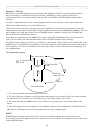
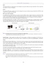
Network - UPnP™
The camera includes support for UPnP™, which is enabled by default. If also enabled on your computer, the
camera will automatically be detected and a new icon will be added to “My Network Places.”
Note: UPnP must also be enabled on your Windows XP or ME computer. To do this, open the Control Panel from the Start Menu and select
Add/Remove Programs. Select Add/Remove Windows Components and open the Networking Services section. Click Details and then
select UPnP as the service to add.
Network - RTP / MPEG-4
These settings are the port range, IP address, port number (video and audio), and Time-To-Live value to use for
the video stream(s) in multicast MPEG-4 format. Only certain IP addresses and port numbers should be used for
multicast streams. For more information, please see the online help.
Network - Bonjour
The AXIS 212 PTZ includes support for Bonjour. When enabled, the camera is automatically detected by
operating systems and clients that support Bonjour.
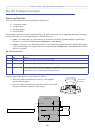
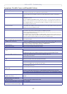
Ports & Devices
I/O Ports - the pinout, interface support and the control and monitoring functions provided by this connector
are described in
The I/O Terminal Connector, on page 40.
LED Settings
The Status indicator LED on the front of the camera can be set to flash at a configurable interval (or to not light
up at all) whenever the unit is accessed. For a listing of all LED behavior, see
page 7, or the online help.
Note that the LED does not flash when the stream is retrieved using MPEG-4 multicast.