


AXIS 212 PTZ - The I/O Terminal Connector
40
The I/O Terminal Connector
Pinout and Interface
The 4-pin I/O terminal connector provides the interface to:
• 1 transistor output
• 1 digital input
• Auxiliary power
• Ground (GND)
The terminal connector is used in applications for e.g. motion detection, event triggering, time lapse recording,
alarm notification via email, image storage to FTP locations, etc.
• Input - for connecting e.g. a push button. If the button is pressed, the state changes and the input
becomes active (shown under Event Configuration > Port Status).
• Output - connects e.g. an alarm device that can be activated by Output buttons on the Live View page,
or by an Event Type. The output will show as active (Event Configuration > Port Status) if the alarm
device is activated.
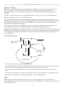
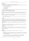
I/O terminal
connector
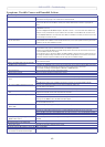
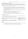
I/O terminal connector:
Connect input/output devices to the camera as follows:
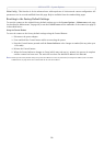
o
z
AXIS 212 PTZ
3.3V, max. 50mA
e.g.
doorbell
4
o
3
o
o
2
1
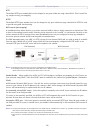
Terminal Connectors - Schematics
1. Attach the cables for the device securely to the supplied
green connector block.
2. Once the cables are connected, push the connector block into
the green terminal connector on the camera.
Pin Function Description
1 GND Ground
23.3V DC
Can be used to power auxiliary equipment, max 50mA.
3 Digital Input Connect to GND to activate, or leave floating (or unconnected) to deactivate.
4 Transistor Output With a maximum load of 50mA and a maximum voltage of 24V DC, this output has an open-collector NPN tran-
sistor with the emitter connected to the GND pin. If used with an external relay, a diode must be connected in
parallel with the load, for protection against voltage transients.