


6
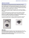
AXIS 231D/232D - AXIS 231D/232D
Hardware Inventory
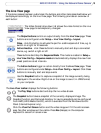
Check the items supplied with your network dome camera against the following list:
Item Title/variant Notes
Network Dome Camera AXIS 231D/232D
Printed user documentation AXIS 231D/232D Installation
Guide
Warranty Warranty document
Connection module Connection module Power/alarm connections
Cable 22-pol connection cable 24V AC, 3A power connection
I/O connections
Power supply Country specific
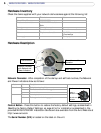
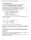
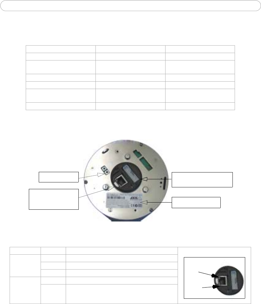
Hardware Description
Serial number
Connection module
connector
Network connector
S/N
with Network and
Power Indicators
Control button
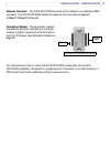
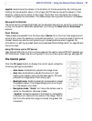
Network Connector- After completion of the startup and self test routines, the Network
and Power Indicators show as follows:
Indicator Color Description
Detail - network connector:
Network
Indicator
Power
Indicator
Network Green Flashes for network activity
Red Slow flash for failed firmware upgrade
None No connection
Power Green Normal operation
Amber Flashes green/amber during upgrade.
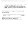
Control Button - Press this button to restore the factory default settings, as described in
Resetting to Factory Default Settings, on page 43 or for installation as described in the
provided AXIS 231D/232D Installation Guide and also available from the Axis Web site at
http://www.axis.com.
The Serial Number (S/N) is located on the label on the unit.