


VIP X1 | Installation and Operating Manual EN | 21
Bosch Security Systems | 2006-12 | V2.5 Installation
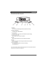
The stereo jack plugs must be connected as follows:
– Connect an audio source with line level to the Line In jack socket of the
VIP X1 with a 3.5 mm stereo jack plug.
– Connect a unit with line-in connection to the Line Out jack socket of the
VIP X1 with a 3.5 mm stereo jack plug.
If you wish to connect a microphone and a loudspeaker directly:
– Connect the microphone cords to the MIC and GND connections on the push-
in terminal.
– Connect the loudspeaker cords to the SPK connections on the push-in termi-
nal.
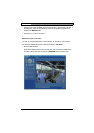
Data interface
The bidirectional data interface is used to control units connected to the VIP X1,
such as a dome camera with a motorized lens.
The interface supports the RS232, RS422 and RS485 transmission standards.
The interface is made up of four terminals of the ST500 jack (for pin assignment,
see page 127).
The range of controllable equipment is expanding constantly. The manufactur-
ers of the relevant equipment provide specific information on installation and
control.
Caution
Please take note of the appropriate documentation when installing and op-
erating the unit to be controlled. The documentation contains important
safety instructions and information about permitted uses.
Note
A video connection is necessary to transmit transparent data.
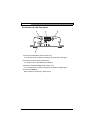
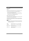
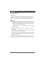
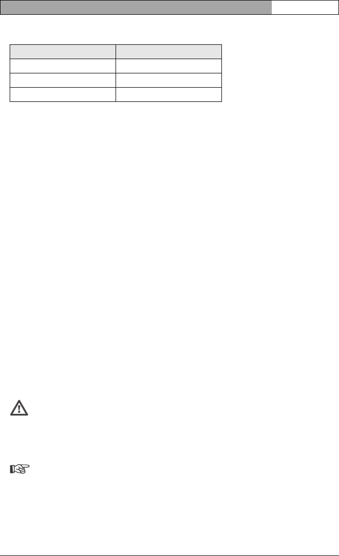
Contact Function
Tip Channel 1 (camera)
Middle ring Not used
Lower ring Ground