


12
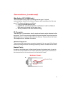
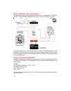
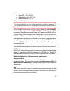
Basic Hardware Set-up Diagram
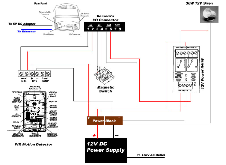
The diagram below shows the hardware configuration for 1 Active Sensor (PIR Motion
Sensor), 1 Passive Sensor (Magnetic Switch), and 1 output (For Relay) for a siren.
Passive Component Notes!!!
Only simple magnetic or contact switches can be used for Passive components. This
limitation is by the camera only supplying 5V and less then 100mA current to those
circuits. Distance for passive components is limited by a viewable camera range of about
25 Ft using 26GA wire.
Active Component Notes!!!
A separate power supply is needed for these devices. In order to choose the proper PS.
The total current draw by all the components cannot exceed the Max supplied by the
power supply.
Example
Our PIR Motion Detector = 17 mA = .017A
Our Relay = 60 mA = .06A
Siren = 200mA = .20A
Total : .277A
Purchased DC power adapter 12V DC 1.2A Max to cover all Active Sensors and Siren,
with room to grow.