


7
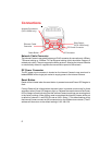
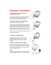
Slide Switch (DCS-1000W only)
The slide switch permit user’s to determine the type of network
communication media for the Internet Camera and is positioned on the rear
panel. The three settings are as follows:
• LAN (Local Area Network Only)
• LAN/WLAN (Local Area Network and Wireless Local Area Network.
Both can be accessed at the same time.)
• WLAN (Wireless Local Area Network Only)
I/O Connector
There are four I/O connectors, two for input and two for output situated on the
rear panel. The I/O connectors provide the physical interface to send and receive
digital signals to a variety of external alarm devices. Please refer to the User’s
Guide appendix for detailed information.
Antenna Connector
There are two SMA type antenna connectors located at the rear panel of the Internet
Camera providing connection for two high sensitivity antenna included with the device.
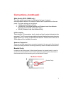
Connections (continued)
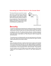
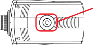
Bottom Panel
Bracket Cavity
Bracket Cavity
Located on the bottom panel of the Internet Camera, the bracket cavity is used to
connect the camera stand onto the Internet Camera by attaching the screw head on
the camera stand into the mounting cavity of the Internet Camera.