


7
BASE MODEL CHARACTERISTICS
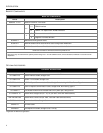
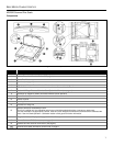
MS2320 Scanner/Diva Scale
Components
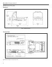
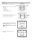
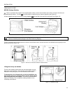
Figure 7. MS2320 Components
ITEM NO. DESCRIPTION OF ITEM
1 Blue and White LED Indicators (see page 29)
2 Volume/Tone Multi-Function Button (see page 34)
3 Scale Zero Button
4 Speaker (see page 29)
5 High Impact Window Frame / Vertical Window (Laser Aperture) (see page 4)
6 Flow Direction Indicators
7 Platter with Finger Recess, Stainless Steel Option Not Shown (see page 4)
8 Diamonex or Sapphire (shown) Horizontal Window (Laser Aperture)
9 Scale Side Guards
10 Debris Channel
11 Leveling Bubble
12 Handles for Lifting Unit
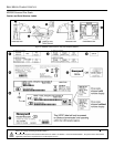
13
Sealed Calibration Switch/Button Cover
On a fully installed unit, the calibration switch cover should be sealed with either a lead wire or paper seal.
The seal indicates if the appropriate Federal, State and Local Weights and Measures authorities have calibrated the
scale. See the Scale Operation: Calibration section of this guide for further information.
14 Diagnostic Indicator Display (see page 31 for Error Codes)
15 Power, Scale and EAS Connectors (see page 8)
16 Interface and Aux Scanner Connectors (see page 8)
Scanner/Scale label information can be found on page 9.