


18
INSTALLATION
CABLE INSTALLATION (INTERFACE SPECIFIC)
F
ULL SPEED USB
The following steps describe how to properly install the cables for a Full Speed USB StratosH application. The scanner/scale must
then be configured to match the host’s USB parameters. Cable installation alone does not guarantee that the StratosH will
communicate properly with the host system.
Configuration bar codes are located in the MetroSelect Configuration Guide (PN 00-02407x) and the MS2x20 Stratos Series
Scanner/Diva Scale Configuration Addendum (PN 00-02272x).
1. Turn off the host system.
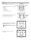
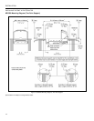
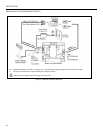
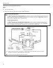
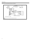
2. Plug the 10-pin RJ45 end of the USB interface cable (PN 57-57200x-N-3 or 57-57006x-N-3) into the 10-pin socket labeled,
Scanner USB to Host, on the bottom of the StratosH. Refer to Figure on page 20.
3. Connect the other end of the USB interface cable to the appropriate USB port on the host device.
Before continuing verify that the USB interface cable is connected to the appropriate socket on the scanner. An incorrect
cable connection can cause communication problems or potential damage to the scanner and/or terminal.
Manufacturers Note: Plugging the scanner into the USB port of the host does not guarantee that scanned information will
appear at the host. A software driver and correct configuration setting are also required for proper communication to occur.
When using the RS232/Full Speed USB/RS485 (-121) interface, the USB and RS485 interfaces are not active at the same
time.
Steps 4 and 5 are for dual cable interfaces where the scale and the scanner connect to the host with their own separate
communication cables. Skip to step 6 for a single cable interface where the scale and scanner connect to the host with a single cable.
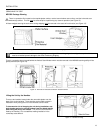
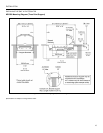
4. Plug the dual interface cable (
PN 57-57000x-N-3) into the 10-pin socket labeled, Scale RS232 to Host, on the bottom of the
StratosH.
5. Connect the other end of the dual interface cable (PN 57-57000x-N-3) to the appropriate communication port on the host’s scale
device.
6. Plug the optional remote display cable** into the 10-pin socket labeled, Scale to Display, on the bottom of the StratosH.
** See page 3 for information on optional display types and part numbers.
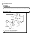
7. Plug the external power supply (PN 46-46xxx) into the 3-pin Molex socket labeled, DC Power In, on the bottom of the StratosH.
xxx* Specifies international connection. See Optional Accessories in the Introduction section of this guide for a complete listing.
Check the AC input requirements of the power supply to make sure the voltage matches the AC outlet. The outlet should
be located near the equipment and be easily accessible.
Honeywell recommends using a switched AC outlet. The switch should be located on the operator’s side of the checkout
counter in close proximity to the StratosH to facilitate calibration and service of the unit.
8. Connect AC power to the transformer. If the AC outlet is equipped with an on/off switch, turn the power on.