


Page 5
Installation
TM-6710/6710CL High-Speed Progressive Scanning CCD Camera
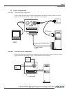
2.2 Camera Setup
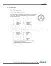
2.2.1 Pin Configurations
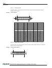
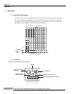
2.2.1 (a) 12-Pin Connector (TM-6710)
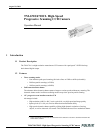
The TM-6710 has a 12-pin connector for power input. Pin #1 is Ground and Pin
#2 is +12V DC. The other pins handle a number of other input and output
functions, as detailed below.
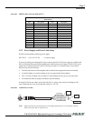
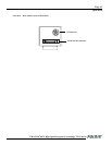
2.2.1 (b) 12-Pin Connector (TM-6710CL)
The TM-6710CL has a 12-pin connector for power input. Pin #1 is ground and Pin #2 is +12V DC. The
pinout table is shown below. For the TM-6710CL, serial communication camera control is done via the
Camera Link connector on the rear panel of the camera.
Pin Description Pin Description
1 GND (Power) 7 VD In
2+12V DC 8N/C
3 GND (Analog) 9 HD In
4 Video Out 10 RXD (RS-232)
5 GND (Digital) 11 Integration
6 VINIT In 12 TXD (RS-232)
Pin Description Pin Description
1 GND (Power) 7 VD In
2+12V DC 8N/C
3 GND (Analog) 9 HD In
4Video Out 10
RXD
*
*. Optional TTL serial communications.
5 GND (Digital) 11
Integration
†
6
VINIT In
†
†. VINIT and Integration can be controlled via Camera Link.
When Camera Link is connected for these uses, do not use
the 12-pin connector inputs.
12 TXD*
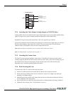
1
2
3
4
5
6
9
8
7
11
12
10