


Page 3
Introduction
TM-6710/6710CL High-Speed Progressive Scanning CCD Camera
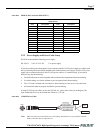
1.4 System Configuration
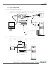
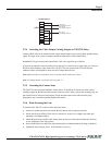
FIGURE 1. TM-6710 System Configuration
Figure 1 below presents a typical system configuration for the TM-6710 camera. Please see “Power
Supply and Power Cable Setup” on page 7 for info on power supplies.
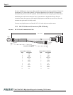
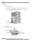
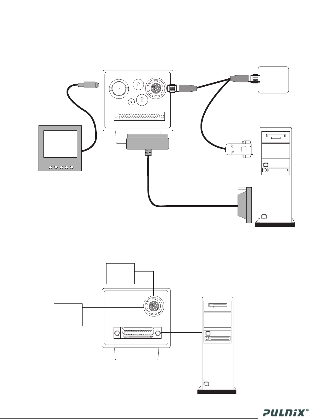
FIGURE 2. TM-6710CL System Configuration
Figure 2 below presents a typical system configuration for the TM-6710CL camera. Please see “Power
Supply and Power Cable Setup” on page 7 for information on power supplies.
VIDEO
POWER
SHUTTER
0
1
2
3
4
5
6
7
8
9
DWN
UP
MODE
DIGITAL
1
0
2
3
4
5
6
7
8
9
A
B
C
D
E
Frame Grabber
Board
Multi Sync
Analog
Monitor
Ext. Sync
Power
Trigger
Analog video
RS-232
P/N: CS-232-B912
Digital cable: P/N 50DG-02LP
POWER
CAMERA LINK
External Sync.
Power
Trigger
Analog video
PD-12 (series)
power supply
12P-02S
26CL-02-26