


Page 8
Installation
TM-6710/6710CL High-Speed Progressive Scanning CCD Camera
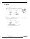
If you are building your own power cables, consult the pin-out for the camera purchased. Connect the
Ground and +12V power leads of the PC-12P power connector to Pin #1 and Pin #2, respectively.
Remember that power must be DC regulated, and of sufficient current to properly power the camera.
Attach the power cable to the connector. The 12-pin connector is keyed and will only fit in one
orientation. Rotate the connector while applying slight pressure until the keyways line up. Press the
connector into place until it is firmly seated.
You may now plug the power cord into the 110V AC socket and power up the camera.
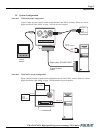
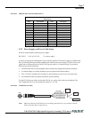
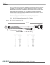
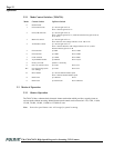
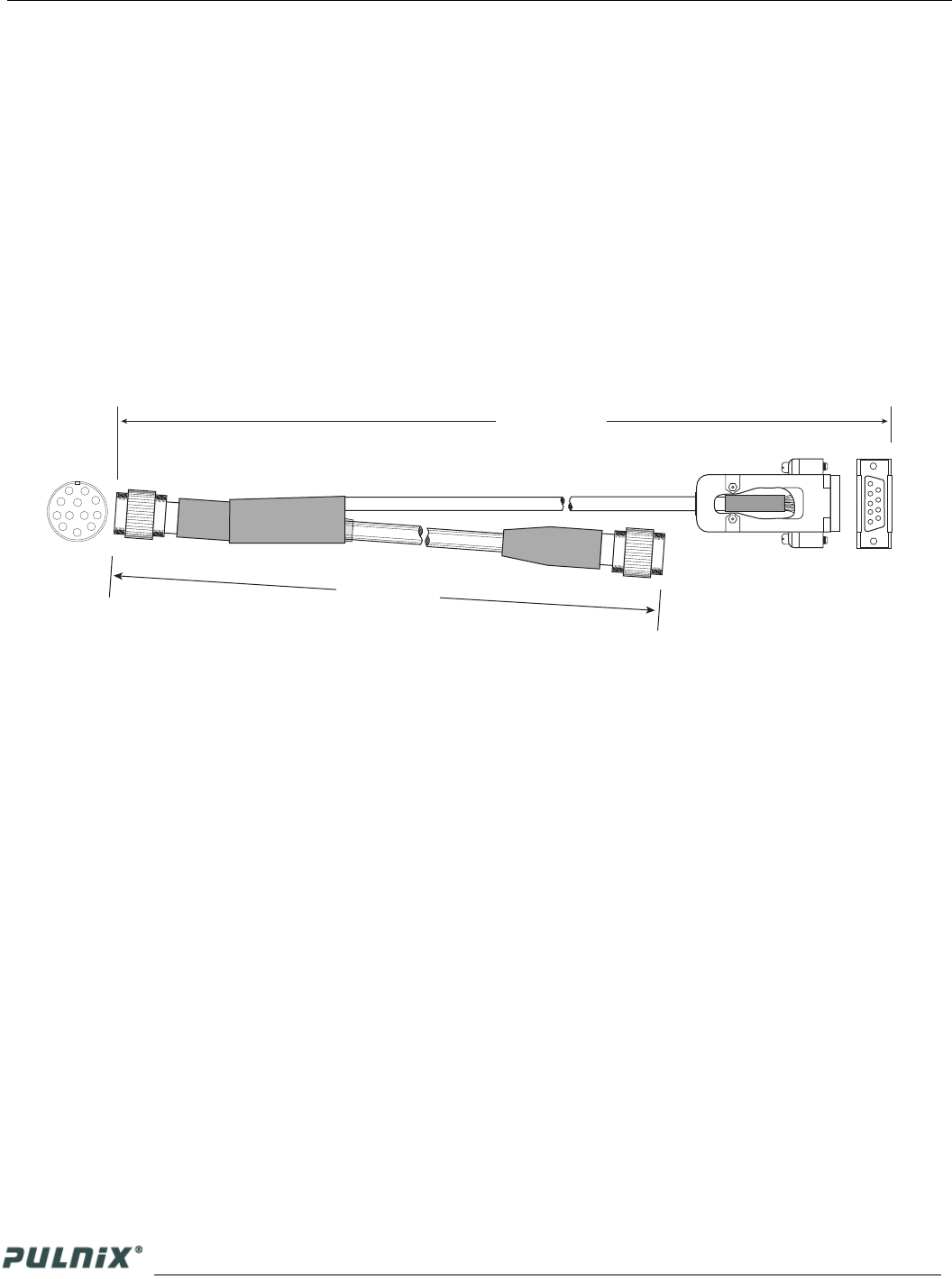
2.2.3 RS-232 Cables and Connectors (TM-6710 only)
FIGURE 7. RS-232 Serial Communication Cable
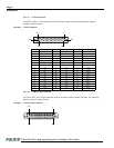
12-Pin Male Connector 12-Pin Female Connector
Pin# Description Pin# Description
1 GND 1 GND
2 +12V 2 +12V
3 GND 3 GND
4 Video Out 4 Video Out
5 GND 5 GND
6 VINIT 6 VINIT
7 VD In 7 VD In
8N/C 8 N/C
9 HD In 9 HD In
10 N/C 10 RXD
11 INTEG 11 INTEG
12 N/C 12 TXD
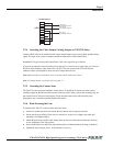
MALE
FEMALE
9
1
5
To: Computer
Com Port
To: Power &
Sync Box
To: Camera
1
5
6
9
8
7
11
12
10
6
3
2
4
2000 ± 20mm
265mm ± 5mm
Part # CS-232-B912