


Page 21
Operation
TM-6710/6710CL High-Speed Progressive Scanning CCD Camera
1. Report from RAM “R R” command. Reads out the current setting. The response format from the
camera is:
“:”, ASK, “RR”,[data] (12 x 2 bytes ASCII), CR
2. Report from pages “RP 0-6” command. Camera responds:
“:”, ASK, “P”, “0-6” (page), (12 x 2 bytes ASCII), CR
3. Report from user calibration table “R U”, “A-D” command. Camera response is:
“:”, ACK, “U”, “A-D”, [data] 5 x 2 bytes (first five value above twelve value)
4. Report from factory set “R S”, “A-D” command. Camera response is:
“:”, ACK, “S”, “A-D”, [data] 5 x 2 bytes (first five value above twelve value)
Command C
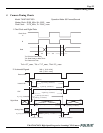
Pixel Clock Speed (frame rate 120/60Hz)
Clock/2: “:”, “C”, “1”, CR
3AH, 43H, 31H, 0DH
Master Clock: “:”, “C”, “0”, CR
3AH, 43H, 30H, 0DH
Note: When RS-232C is active, back plate switches are overwritten and do not function. In order
to activate back plate switches, power off and power up again.
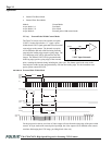
1. Main Gain (ch. A and ch. B)
2. Ch. A fine tune gain
3. Ch. B fine tune gain
4. Ch. A video voltage reference
5. Ch. B video voltage reference
6. Reserved
7. Video voltage reference top
8. Reserved
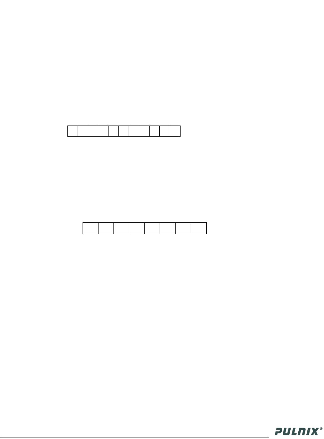
9. Function flag
10. Shutter dial switch valve
11. Normal shutter value
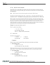
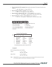
8 8 8 8 8 8 8 8 8 8 16
1 2 3 4 5 6 7 8 9 10 11
For detailed parameters, please contact PULNiX.
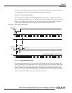
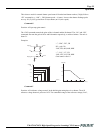
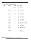
Bit
Description
Clock Selection
Sync Output
Shutter
Shutter Control
Async Mode
Shutter Mode
Partial Scan 0
Partial Scan 1
1- 60 Hz
1- “One Shot”
1- On
1- Direct
1- Pulse Width
1- Async
11- 120 Hz
10- 100 Lines
0- 120 Hz
0- Continuous
0- Off
0- Normal
0- Normal
0- Normal
01-200 Lines
11- N/A
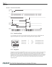
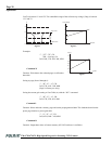
Function Flag Description
7 6 5 4 3 2 1 0
Bit
0
1
2
3
4
5
6
7