


Page 7
Installation
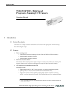
TM-6710/6710CL High-Speed Progressive Scanning CCD Camera
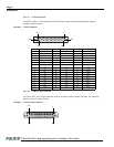
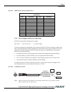
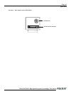
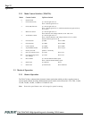
FIGURE 5. MDR 26-Pin Connector (0226-622VC)
2.2.2 Power Supply and Power Cable Setup
PULNiX recommends the following power supply:
PD-12UUP 110V AC/12V DC 1.2A power supply
If you are providing power through the 12-pin connector, the PD-12UUP power supply is available with
the 12-pin mating connector already attached to the leads from the power supply. The PD-12UU power
supply can be connected directly to the PULNiX power cable or via a terminal strip. If you choose
direct wiring, note the following:
• The lead ends must be twisted together and tin-soldered for strength and electrical continuity.
• Use shrink tubing or a similar insulator to prevent exposed leads from touching.
• The +12V lead is marked with a red stripe or white lettering; be sure not to reverse the leads.
• All connections must be properly insulated to prevent shorting.
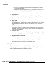
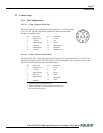
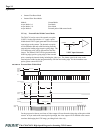
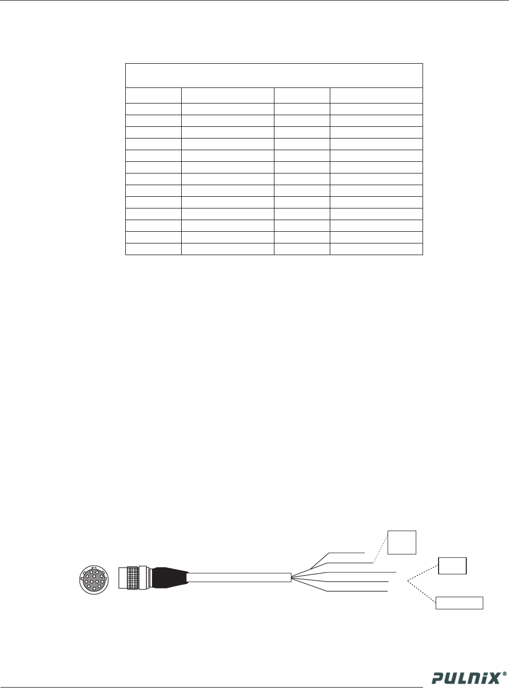
If using PULNiX power cables, such as the 12P-02S, etc., please refer to the pin-out diagram. The
color-coded leads use Gray for Ground and Yellow for +12V DC.
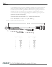
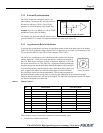
FIGURE 6. 12P-02S Power Cable
Note: Make sure that the unused leads are not touching and that there is no possibility that the
leads could short due to exposed wires.
MDR 26-Pin Connector
(0226-622VC)
Pin# Description Pin# Description
1 GND (shield) 14 GND (Shield)
2X0-15X0+
3X1-16X1+
4X2-17X2+
5Xclk-18Xclk+
6X3-19X3+
7 SerTC+ 20 SerTC-
8 SerTFG- 21 SerTFG+
9 VINIT (CC1-) 22 VINIT (CC1+)
10 INTEG (CC2+) 23 INTEG (CC2-)
11 CC3- 24 CC3+
12 CC4+ 25 CC4-
13 GND (shield) 26 GND (Shield)
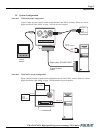
HD In (White Coax)
Video Out (Red Coax)
VD In (Black Coax)
Power (Yellow)
+12 V
Monitor
Frame Grabber
GND (Gray)
}
Male