


14
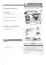
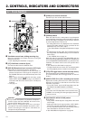
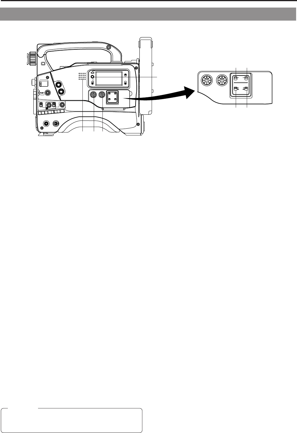
2. CONTROLS, INDICATORS AND CONNECTORS
1
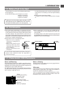
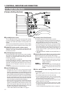
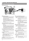
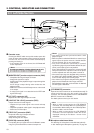
Monitoring loudspeaker
• Enables EE monitoring of the input audio signal during
recording, in the record-pause mode or in the stop mode.
Outputs the playback sound in the playback mode.
The sound to be output can be selected using the
MONITOR SELECT switch
4
.
• The loudspeaker volume can be adjusted with the
MONITOR volume control
2
on page 12.
The audio from the loudspeaker is not output when an
earphone is plugged into the EARPHONE jack
2
on page
20. The warning alarm tones are also output through this
loudspeaker.
☞ See “ALARM INDICATIONS” on pages 86.
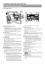
2
[CH1 AUDIO LEVEL] CH1 recording level control
Adjust the recording level of the CH1 audio channel with
this control.
• To use this control, set the CH1 AUDIO SELECT switch
5 to “MANUAL”.
This control works regardless of the setting of the VCR
Setup Menu item No. 246 FRONT VOLUME ENABLE.
To use this control, set the AUDIO LEVEL CH-1 recording
level control (7 on page 10) on the front section to the
maximum (10) position, or set the VCR Setup Menu item
No. 246 FRONT VOLUME ENABLE to “DISABLE”.
3
[CH2 AUDIO LEVEL] CH2 recording level control
Adjust the recording level of the CH2 audio channel with
this control.
• This control is valid only when the CH2 AUDIO SELECT
switch
6
is set to "MANUAL".
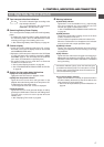
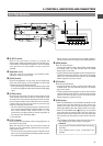
4
[MONITOR SELECT] audio monitor selector
switch
This switch is used to select the monitor sound output from
the MONITORING LOUDSPEAKER 1 or via the
EARPHONE jack 2 on page 20.
CH-1 :The CH1 channel audio is output.
MIX : CH1 and CH2 channel audio are output mixed.
CH-2 :The CH2 channel audio is output.
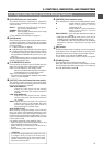
5
[CH-1 AUDIO SELECT] selector switch
This switch is used to select the method for adjusting the
recording level of the CH-1 audio channel.
AUTO : The recording level is held at the reference level
even when sounds greater than the reference
level are input.
The recording level does not increase when the
input level is low.
MANUAL
: The recording level can be adjusted with the CH-
1 AUDIO LEVEL control
2
or the CH-1 AUDIO
LEVEL control
7
on page 10.
To use the AUDIO LEVEL CH-1 recording level
control on the front section, set the VCR Setup
Menu item No. 246 FRONT VOLUME ENABLE
to “ENABLE”.
6
[CH-2 AUDIO SELECT] selector switch
This switch is used to select the method for adjusting the
recording level of the CH-2 audio channel.
AUTO : The recording level is held at the reference level
even when sounds greater than the reference
level are input.
The recording level does not increase when the
input level is low.
MANUAL
: The recording level can be adjusted with the CH-
2 AUDIO LEVEL control
3
.
7
[CH-1 AUDIO INPUT] selector switch
This switch is used to select the input section of the CH1
audio channel.
FRONT : The sound from the MIC IN connector on the
front side section is input.
REAR :The sound from the CH-1 AUDIO IN connector
on the rear side section is input.
8
[CH-2 AUDIO INPUT] selector switch
This switch is used to select the input section of the CH2
audio channel.
FRONT :The sound from the MIC IN connector on the
front side section is input.
REAR :The sound from the CH-2 AUDIO IN connector
on the rear side section is input.
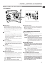
[Audio Setting Section]
2-2 Right Side Section (Cont'd)
qwe
r
ty
ui
LIGHT
ON
OFF
COUNTER
CTL
TC
UB
RESET
OPERATE/WARNING
MONITOR
SELECT
STATUSSHUTTER
MENU
FILTER
1 3200k
2 5600k
3 5600k+ND
POWER
NG
GAIN
OUTPUT
WHT.BAL
VTR
ON OFF
ALARM
MONITOR
CH-1
CH-2
AUDIO
LEVEL
AUTO IRIS LOLUX
BACK L
NORMAL
SPOT L
STRETCH
NORMAL
COMPRESS
FULL AUTO BLACK
HML
SAVE STBY
BARS CAM
ON
OFF
AUTO KNEE
PRST A B
CH-1
CH-2
AUDIO
LEVEL
CH-1 CH-2
AUTO
MANUAL
FRONT
REAR
AUDIO SELECT
AUDIO INPUT
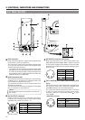
CAUTION:
Make sure to move switches all the way. Do not leave a
switch stopped in a midway position. Noise will be
generated and operation irregularities will occur.