


67
12. SETUP MENU
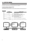
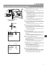
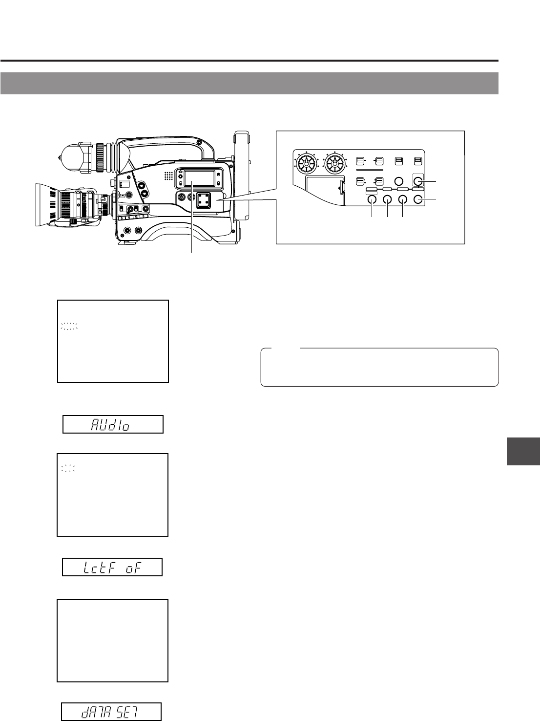
DISPLAYING AND SETTING VCR SETUP MENUS
1.
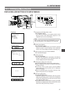
Engaging the VCR Setup Menu mode.
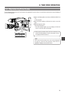
Press the MENU button.
• The "MENU" indication in the display section starts
blinking and the VCR Setup Menu appears in the
viewfinder and on the counter display.
2.
Selecting the GROUP.
Press the GROUP button.
• Each time the GROUP button is pressed the selected
GROUP number is shown blinking on the viewfinder
screen. The counter display shows the selected group.
3.
Open the Item menu of the selected GROUP.
Press the SELECT button.
4.
Selecting the Item.
Press the ITEM button.
• Each time the ITEM button is pressed the selected item
number is shown blinking on the viewfinder screen. The
counter display shows the selected item.
5.
Changing the setting value of the item.
Press the SELECT button and select the setting value.
Ⅲ When multiple items should be set, repeat the operations
of steps
4.
and
5
.
Ⅲ To set menu items in other groups, press the MENU
button. When the relevant group menu is displayed,
perform the setting.
Ⅲ When the GROUP button is pressed, the items of the
higher order group menu are displayed.
6.
Saving the setting value.
Press the DATA SET button.
• "DATA SET" appears in the viewfinder and on the counter
display and the setting value is saved in the GY-DV500's
memory. The display returns to the normal screen mode
when data has been saved.
Ⅲ If the MENU button is pressed without pressing the DATA
SET button, the display returns to the normal screen mode
without the setting value being changed.
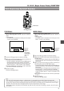
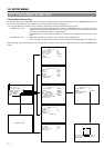
GROUP menu screen
Viewfinder
Item menu screen
DATA SET display
Counter display
000 :SERVO/SYSTEM
100 :VIDEO
200 :AUDIO
300 :SYSTEM
400 : T IME CODE
500 :ON SCREEN
HM : HOUR METER
244:LOWCUT
OFF
245:SAMPLE RATE
48K
246:FRONT
DATA SET
VOLUME
ENABLE
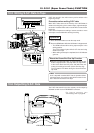
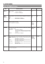
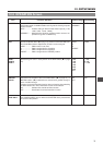
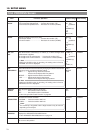
12-1 VCR Setup Menu (Cont'd)
LIGHT
ON
OFF
COUNTER
CTL
TC
UB
RESET
OPERATE/WARNING
MONITOR
SELECT
STATUSSHUTTER
MENU
FILTER
1 3200k
2 5600k
3 5600k+ND
POWER
NG
GAIN
OUTPUT
WHT.BAL
VTR
ON OFF
ALARM
MONITOR
CH-1
CH-2
AUDIO
LEVEL
AUTO IRIS LOLUX
BACK L
NORMAL
SPOT L
STRETCH
NORMAL
COMPRESS
FULL AUTO BLACK
HML
SAVE STBY
BARS CAM
O
N
O
FF
AUTO KNEE
PRST A B
TC GENERATOR
FREE
REC
PRESET
REGEN
CH-1
CH-2CH-1
CH-2
CH-1 CH-2
CONTINUE MENU
PRESETADVANCESHIFTHOLD
AUTO
MANUAL
FRONT
REAR
DATA SET
SELECTITEMGROUP
AUDIO SELECT
AUDIO INPUT
AUDIO
LEVEL
LITHIUM BATT.
"MENU" indication
2. 3. 5.4.
6.
1.
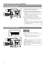
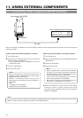
Note:
When a cable is connected to the VTR REMOTE connector,
the VTR Setup Menu is not displayed in the viewfinder.