


46
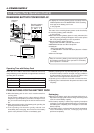
6. SETTING AND ADJUSTMENTS BEFORE SHOOTING
LIGHT
ON
OFF
COUNTER
CTL
TC
UB
RESET
OPERATE/WARNING
MONITOR
SELECT
STATUSSHUTTER
MENU
FILTER
1 3200k
2 5600k
3 5600k+ND
POWER
NG
GAIN
OUTPUT
WHT.BAL
VTR
ON OFF
ALARM
MONITOR
CH-1
CH-2
AUDIO
LEVEL
AUTO IRIS LOLUX
BACK L
NORMAL
SPOT L
STRETCH
NORMAL
COMPRESS
FULL AUTO BLACK
HML
SAVE STBY
BARS CAM
ON
OFF
AUTO KNEE
PRST A B
TC GENERATOR
FREE
REC
PRESET
REGEN
CH-1
CH-2CH-1
CH-2
CH-1 CH-2
CONTINUE MENU
PRESETADVANCESHIFTHOLD
AUTO
MANUAL
FRONT
REAR
DATA SET
SELECTITEMGROUP
AUDIO SELECT
AUDIO INPUT
AUDIO
LEVEL
LITHIUM BATT.
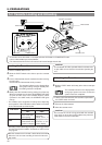
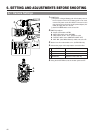
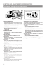
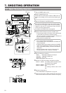
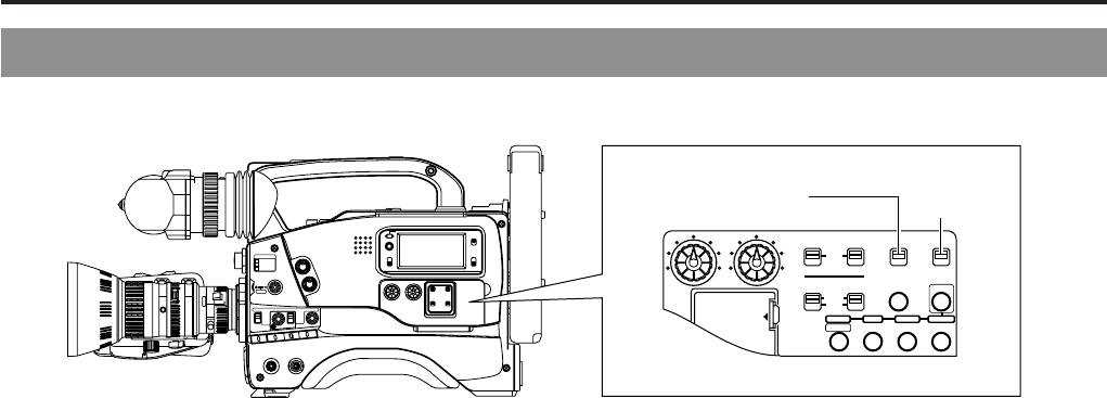
6-6 Switch Settings of the VCR Section
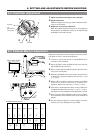
Ⅲ Audio input signal selection
Use the AUDIO INPUT switch to select whether the sound
recorded on audio channel 1 or 2 is the sound from the
microphone connector on the front section or the sound from
the AUDIO INPUT connector on the rear section.
☞ See page 47.
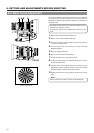
Ⅲ Audio recording level adjustment selection
Select "AUTO" or "MANUAL" for the recording level
adjustment mode for each audio channel.
☞ See page 48.
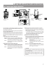
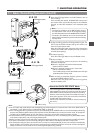
Ⅲ VCR Setup Menu setting
● REMOTE SELECT
Confirm that “LOCAL” is selected if you want to operate on
the GY-DV500 only.
● BACK TALLY MODE
Select the lightning pattern of the BACK TALLY lamp.
● INPUT SELECT
Select the input video signal. To record the GY-DV500's
camera image, set to "CAMERA".
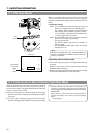
● LOW CUT IN
For each audio input connector, select whether or not the
lower frequency components of the audio signal are cut.
Set to this position to eliminate the wind noise of the
microphone.
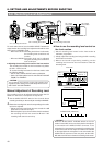
● SAMPLING RATE
Select the sampling rate for audio recording (48 kHz or 32
kHz).
● FRONT VOLUME ENABLE
Set whether or not the front section's audio volume control
should be used. The front section's audio volume control only
affects the CH1 audio channel.
● LONG PAUSE TIME
Select the time (in minutes) until the GY-DV500 enters the
tape protection mode (drum rotation stops) when the record-
pause mode is continued for long time.
● SSF MODE
Select the mode of the S.S.F. (Super Scene Finder) function.
S.S.F. function: Stores the time code of desired scenes or
cue points in the unit's memory.
☞ See “S.S.F. function” on page 60.
● DISPLAY SELECT
Select the counter display (time code or date/time indication)
when the COUNTER switch is set to “TC” or “UB”.
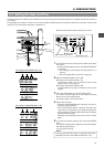
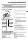
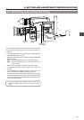
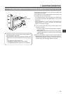
Ⅲ Setting the time code recording function
The GY-DV500 records SMPTE-standard time code during
recording. Set the switches according to applications.
● To record a time code as set in the built-in time code
generator:
• Set the PRESET/REGEN switch to PRESET.
• Set the REC/FREE switch.
If it is required to record continual time codes across different
scenes, set the switch to REC.
• VCR Setup Menu setting
Select the time code generator's framing mode as drop
frame or non-drop using the VCR Setup Menu item No. 416
"NON DROP/DROP".
● To record a time code in continuation of the existing time
code on the tape:
• Set the PRESET/REGEN switch to REGEN.
For details on the time code operations including time code
presetting, see "TIME CODE OPERATION" on page 56.
PRESET/REGEN switch
REC/FREE
switch