


6
1. INTRODUCTION
14. OTHERS
14-1 Troubleshooting ........................................................ 86
• Alarm Indications ................................................... 86
• Warnings in Viewfinder........................................... 88
• Troubles with Error Code Outputs .......................... 90
• Troubles without Error Code Outputs ..................... 91
14-2 Hour Meter Display .................................................. 92
14-3 Specifications ........................................................... 93
• Optional Accessories ............................................. 94
• External Dimensions .............................................. 94
11. USING EXTERNAL COMPONENTS
11-1 Connecting a Video Component with DV Connector 64
11-2 Connecting a PC ...................................................... 65
12. SETUP MENU
12-1 VCR Setup Menu ..................................................... 66
• VCR Setup Menu Configuration ............................. 66
• Displaying and Setting VCR Setup Menus............. 67
• VCR Setup Menu Contents.................................... 68
12-2 Camera Menu Screen Flow ..................................... 70
12-3 How to Select from the Camera Menu ..................... 71
12-4 VF Display Screen ................................................... 72
12-5 OPERATION Screen ................................................ 73
12-6 PROCESS Screen ................................................... 74
12-7 ADVANCED PROCESS Screen ............................... 75
12-8 SKIN COLOR ADJUST Screen................................ 75
12-9 FILE MANAGE Screen............................................. 76
12-10
SETUP Screen......................................................... 77
12-11
Resetting of Camera Menu Setting Values .............. 78
13. FEATURES OF THE CAMERA SECTION
13-1 Full-Time Auto White Balance (FAW) ....................... 79
13-2 IRIS (Brightness) Adjustment ................................... 80
• Adjustment of Lens Iris .......................................... 80
•
Zebra Pattern Display during Manual Adjustment ......
80
13-3 Shooting the Screen Image on a Computer Monitor 81
13-4 Gain (Sensitivity) Adjustment ................................... 82
• Gain Switching ....................................................... 82
• Gain Boost under LOLUX Condition ...................... 82
13-5 Switch Setup According to Illumination and Subject 83
• Switch Functions.................................................... 83
• Full Auto Shooting (FAS) Function ......................... 83
13-6 How to Use Skin Detail ............................................ 84
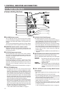
OTHERS
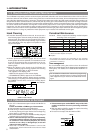
LIGHT
ON
OFF
COUNTER
CTL
TC
UB
RESET
OPERATE/WARNING
MONITOR
SELECT
STATUSSHUTTER
MENU
FILTER
1 3200k
2 5600k
3 5600k+ND
POWER
NG
GAIN
OUTPUT
WHT.BAL
VTR
ON OFF
ALARM
MONITOR
SAVE STBY
H M L
BARS CAM
AUTO KNEE
PRST A B
ON
OFF
CH-1
CH-2
AUDIO
LEVEL
AUTO IRIS LOLUX
BACK L
NORMAL
SPOT L
STRETCH
NORMAL
COMPRESS
FULL AUTO BLACK
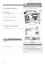
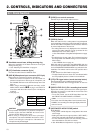
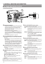
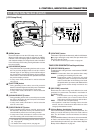
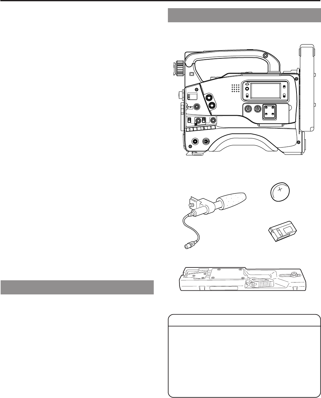
Camcorder (GY-DV500)
The GY-DV500 configuration is as shown below.
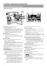
●
The front base mount may be locked while the pin of the
tripod base is not inserted into the hole on the rear base
mount of the unit. Therefore, after mounting, make sure
that these parts are engaged properly.
●
When moving the GY-DV500 mounted on a tripod, any
impact or vibration should be avoided as this may cause
the unit to become detached and to drop from the tripod.
Be sure to remove the unit from the tripod before
transporting it.
1-1 Main Unit Configuration
CAUTION :
CR2032
3V
Lithium battery
Microphone
Head cleaning tape
Tripod base