


65
11. USING EXTERNAL COMPONENTS
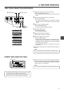
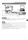
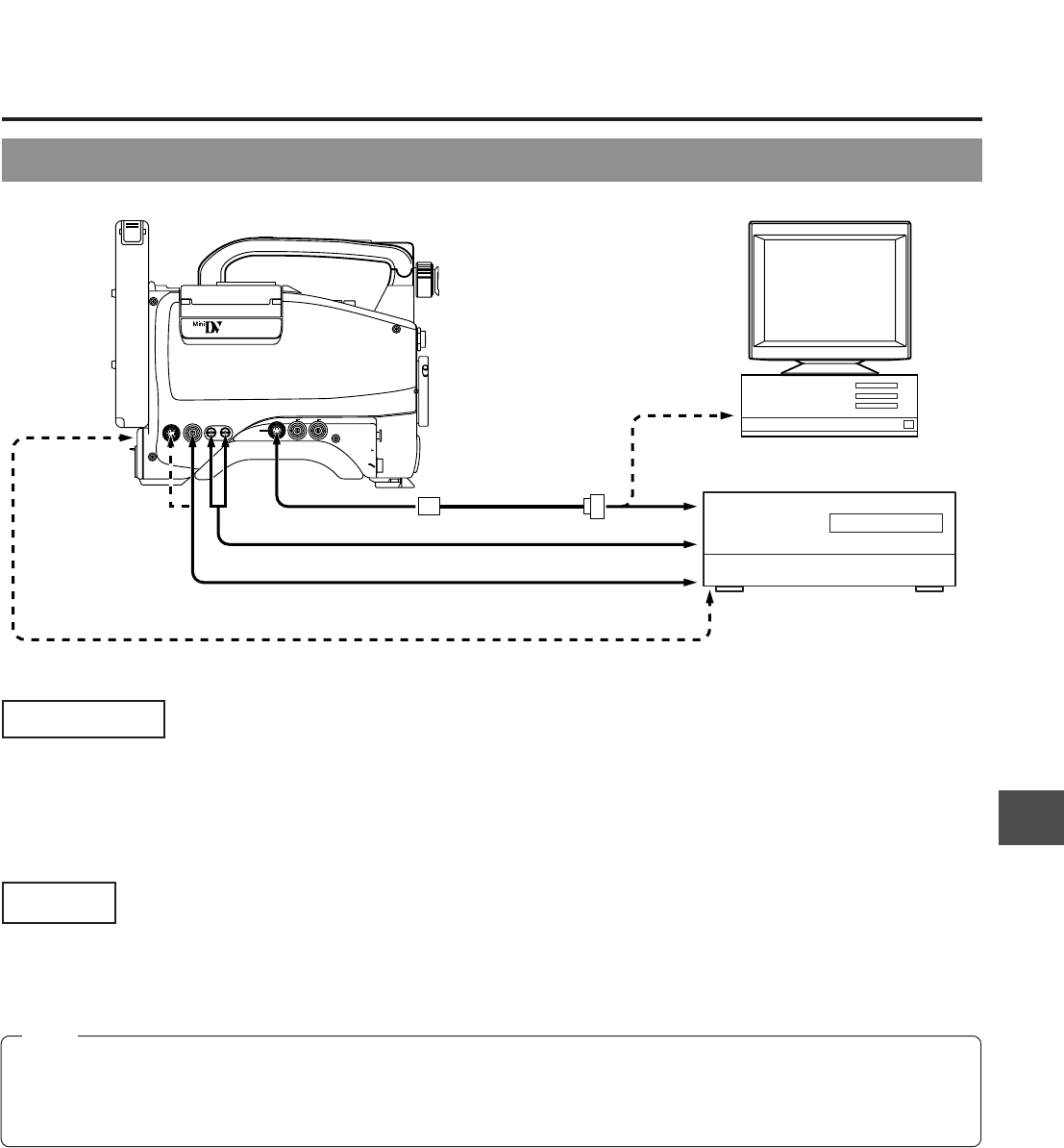
11-2 Connecting a PC
VTR
REMOTE connector
TTL RS-232C
converter cable
(Optional VC-P893)
AUDIO OUT
DV connector
AUDIO IN
VIDEO IN
PC
RS-232C
RS-232C
Non-linear editing controller
DV connector
MONITOR
OUT
connector
VTR
REMOTE
SYNC IN
MIC IN
LENS
TEST OUT
Y/C OUT MONITOR OUT
LINE OUT
CH-1 CH-2
PUSH
DV CAMCORDER
GY-DV500
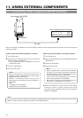
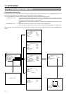
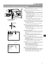
Connections
Connect the GY-DV500's VTR REMOTE connector to the RS-232C connector on the PC or the non-linear editing controller using
the TTL ⇔ RS-232C converter cable.
Or connect the GY-DV500’s DV connector and the DV connector of the non-linear editing controller using a DV cable.
For compatible non-linear editing controller, consult with your JVC dealer.
Settings
• To remote control the PC or non-linear editing controller by means of RS-232C, set the VCR Setup Menu item No. 050 REMOTE
SELECT to "RS232C". ☞ See page 68.
• To remote control the GY-DV500’s VCR using the DV connector’s IEEE1394 option, set the VCR Setup Menu item No. 050
REMOTE SELECT to “IEEE1394”. ☞ See page 68.
Ⅲ The S.S.F. data stored in the unit's memory can be output from the VTR REMOTE connector.
Note:
• When a cable is connected to the VTR REMOTE connector, the VTR Setup Menu is not displayed in the viewfinder. Make
settings on the VTR Setup Menu while the cable is not connected.
• When a cable is connected to the VTR REMOTE connector, the VCR operation mode will not be displayed correctly on the
Status1 screen in the viewfinder.