


16
2. CONTROLS, INDICATORS AND CONNECTORS
LIGHT
ON
OFF
COUNTER
CTL
TC
UB
RESET
OPERATE/WARNING
MONITOR
SELECT
STATUSSHUTTER
MENU
FILTER
1 3200k
2 5600k
3 5600k+ND
POWER
NG
GAIN
OUTPUT
WHT.BAL
VTR
ON OFF
ALARM
MONITOR
CH-1
CH-2
AUDIO
LEVEL
AUTO IRIS LOLUX
BACK L
NORMAL
SPOT L
STRETCH
NORMAL
COMPRESS
FULL AUTO BLACK
HML
SAVE STBY
BARS CAM
ON
OFF
AUTO KNEE
PRST A B
E
REV FWD
FBATT
H
HM
MSF
REMAIN
AUD LOCK
32k
CH 1
CH 2
48k
PB NDF
AUTO OFF DEW
L iRFSERVO
HOLD
SP
MENU
OVER
OVER
40 30 20 10 0
dB
3
4
6
7
8
9
0
A
B
CD
EF5
12
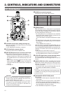
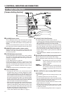
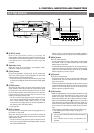
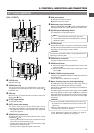
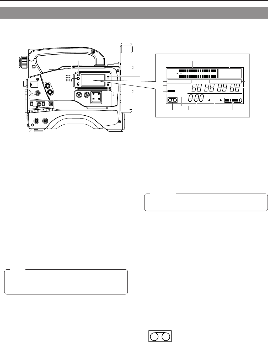
[VCR Display Section]
☞ See “VCR Setup Menu Contents” on page 69.
5
Audio level meters
Show the audio input level of the CH-1 and CH-2 channels
in the record mode or EE mode.
In the playback mode, the meters show the playback audio
level.
"OVER" lights in case of excessive input.
Immediately after the power is switched ON, the level
meters may fluctuate. This is not a malfunction.
6
32K/48K sampling frequency indication
Indicates whether audio recording or playback occurs with
12-bit, 32 kHz sampling or 16-bit 48 kHz sampling.
• In the recording mode, the sampling frequency is set using
the VCR Setup Menu item No. 245 SAMPLING RATE.
In the playback mode, the indication conforms to the
sampling rate of the recorded sound.
7
[AUD LOCK] indicator
Indicates whether the audio signal is locked to the video
signal during recording and playback.
8
[MENU] indicator
Appears when the MENU button
1
on page 15 is pressed
to select the VCR Setup Menu.
9
SP indicator
Indicates the tape speed in record mode.
0
Cassette indicator
Lights when the unit is loaded with a
videocassette. Blinks during ejection or tape
loading.
!
[REMAIN] indicator
The remaining tape time (minutes and seconds) is shown.
For details, see page “Remaining Tape Time Display” on
page 22.
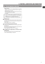
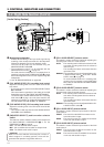
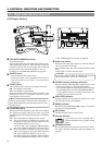
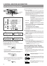
2-2 Right Side Section (Cont'd)
CAUTION:
1
[OPERATE/WARNING] indicator
Normally lights green.
Lights orange during the VTR SAVE (tape protect) mode.
This indicator lights or blinks in red in the case of a warning
condition related to the remaining tape time, remaining
battery power or other abnormal condition in the unit.
For details, see "ALARM INDICATIONS" on pages 86.
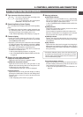
2
[RESET] button
• Press to reset the CTL counter value.
• Pressing the button during presetting of time code or
user's bit resets the time code or user's bit data to
"00:00:00:00".
3
[LIGHT] switch
Turns the illumination of the back-lit display ON or OFF.
ON : The display is illuminated.
OFF : The display is not illuminated.
(Keep this switch at OFF during battery operation of the
GY-DV500 or when it is required to reduce the power
consumption for some reason.)
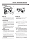
4
[COUNTER] switch
Selects the contents displayed on the LCD counter display.
The displayed contents when TC or UB is set can be
selected using the VCR Setup Menu item No. 516 DISPLAY
SELECT.
CTL : Set to this position to display the CTL counter.
TC : Set to this position to display time codes or for
presetting the time code. (When the Menu item No.
516 DISPLAY SELECT is set to “TC”.)
Time (Hour, Min., Sec.) is displayed. (When the Menu
item No. 516 DISPLAY SELECT is set to “CLOCK”.)
UB : Set to this position to display the user's bits of time
codes or presetting the user's bit. (When the Menu
item No. 516 DISPLAY SELECT is set to “TC”.)
Date (Month, Day, Year) is displayed. (When the Menu
item No. 516 DISPLAY SELECT is set to “CLOCK”.)
Note:
When a videocassette is loaded and the VTR switch is
set to SAVE mode, the illumination will go out even if the
backlight is ON.