


47
6. SETTING AND ADJUSTMENTS BEFORE SHOOTING
LIGHT
ON
OFF
COUNTER
CTL
TC
UB
RESET
OPERATE/WARNING
MONITOR
SELECT
STATUSSHUTTER
MENU
FILTER
1 3200k
2 5600k
3 5600k+ND
POWER
NG
GAIN
OUTPUT
WHT.BAL
VTR
ON OFF
ALARM
MONITOR
CH-1
CH-2
AUDIO
LEVEL
AUTO IRIS LOLUX
BACK L
NORMAL
SPOT L
STRETCH
NORMAL
COMPRESS
FULL AUTO BLACK
HML
SAVE STBY
BARS CAM
ON
OFF
AUTO KNEE
PRST A B
AUTO
WHITE
SKIN
AREA
ACCU
FOCUS
TAKE
VTR
ZEBRA
AUDIO
LEVEL CH-1
ON
OFF
VF
TALLY
DV
AUDIO IN
CH-1
DC INPUT
EARPHONE
DC OUTPUT
LINE MIC
+48V
ON
CH-2
LINE MIC
+48V
ON
CH-1
CH-2
AUDIO
LEVEL
CH-1 CH-2
AUTO
MANUAL
FRONT
REAR
AUDIO SELECT
AUDIO INPUT
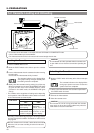
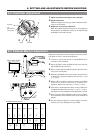
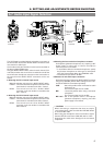
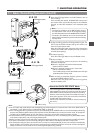
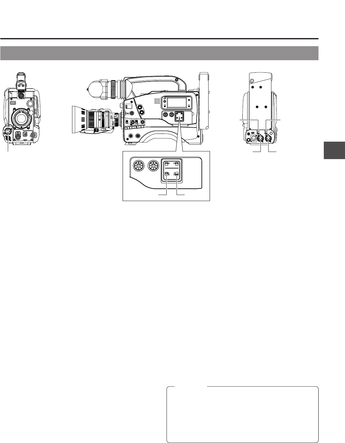
6-7 Audio Input Signal Selection
The GY-DV500 is provided with the microphone connector on
the front section and the two AUDIO INPUT connectors at the
rear section for audio input.
On the other hand, two channels of sound can be recorded on
the tape in digital PCM format.
Using the AUDIO INPUT switch, select for each channel (CH1
and CH2) whether the sound to be recorded should be the
sound from the microphone connector on the front section or
the sound from the AUDIO INPUT connectors on the rear
section.
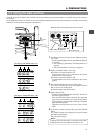
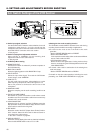
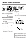
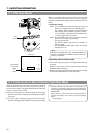
Ⅲ Selecting the CH-1 channel input sound
Make the selection using the CH-1 AUDIO INPUT switch.
FRONT : The sound from the microphone connector on the
front section is recorded on the CH-1 channel.
REAR : The sound from the CH-1 AUDIO INPUT
connector on the rear section is recorded on the
CH-1 channel.
Ⅲ Selecting the CH-2 channel input sound
Make the selection using the CH-2 AUDIO INPUT switch.
FRONT : The sound from the microphone connector on the
front section is recorded on the CH-2 channel.
REAR : The sound from the CH-2 AUDIO INPUT
connector on the rear section is recorded on the
CH-2 channel.
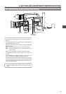
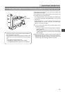
Ⅲ Selecting the front section's microphone connector
A microphone (phantom microphone, etc.) requiring +48 V
power supply or other type of camera microphone
(monaural) can be connected.
• In accordance with the connected microphone, specify
the phantom microphone or other type of microphone
using the Camera Setup Menu item CAM MIC +48V.
• The reference input level is -60 dBs.
Ⅲ Selection of rear audio input connectors
Select the audio signal input to the AUDIO INPUT connector
using the [LINE/MIC] switch. Make settings for the CH-1
and CH-2 AUDIO IN connectors separately.
LINE : Set to this position when connected to audio
equipment, etc.
The reference input level is +4 dBs.
MIC : Set to this position when using a monaural
microphone.
The reference input level is -60 dBs.
MIC +48 V : Set to this position when a microphone
(phantom microphone) requiring +48 V DC
power supply is connected.
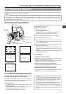
Microphone input
connector
CH-1 AUDIO
LINE/MIC
switch
CH-2 AUDIO
LINE/MIC
switch
CH-1 AUDIO
INPUT
connector
CH-2 AUDIO
INPUT
connector
CH-1 AUDIO
INPUT switch
CH-2 AUDIO
INPUT switch
CAUTION:
When connecting a component that does not require
+48 V power supply, make sure that the LINE/MIC switch
is not set to MIC +48V.
When using the microphone on the front section, set the
Camera SETUP screen item “CAM, MIC, 48V” to “OFF”.
Neglecting this could cause damage to the connected
component.