


E-6
9
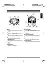
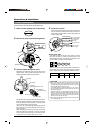
Alarm Output Terminals (CN24)
Output terminals for Alarm 2 and Alarm 3.
Connect the provided cables to these terminals.
☞
P. 15
Pin No. Signal Name Color of Cable
1 Alarm output 2 + Red
2 Alarm output 2 – White
3 Alarm output 3 + Orange
4 Alarm output 3 – Gray
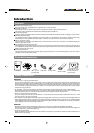
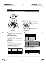
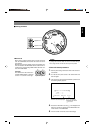
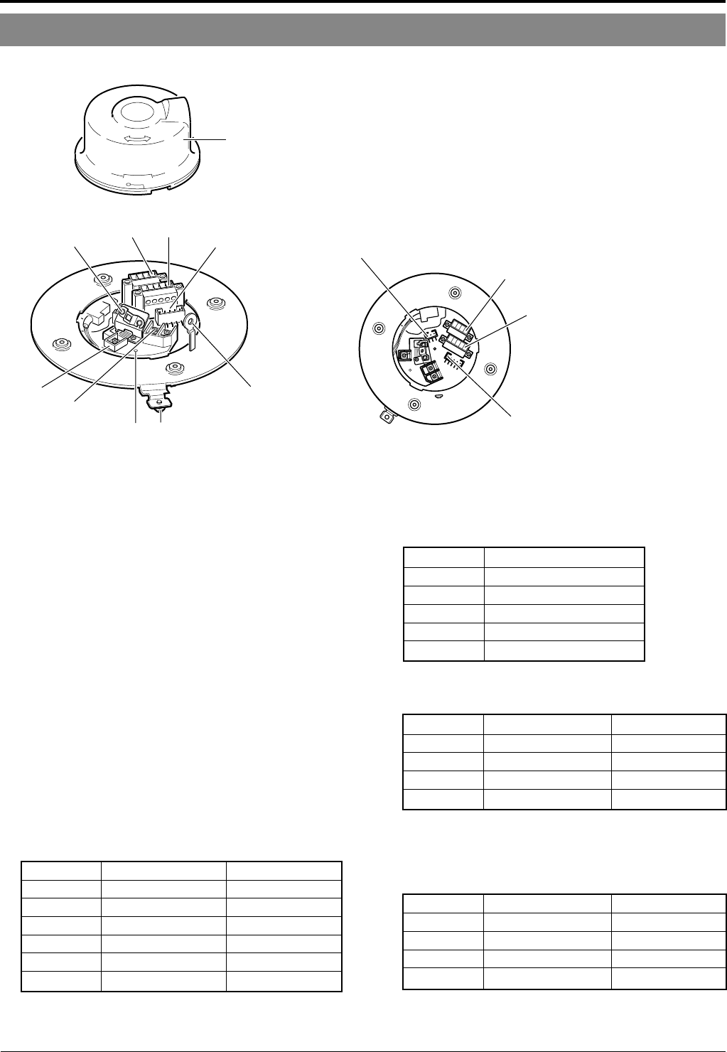
■ Camera body
1
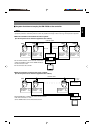
[VIDEO OUT] Coaxial Cable Connectors
Output connector of a composite video signal (1 V(p-p))
with an output impedance of 75 Ω, to be connected to a
switcher, etc.
2
[AC ` 24V INPUT] Connector
Connect to a 24 V AC power supply.
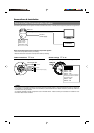
3
Cover Position Alignment Mark
When attaching the cover, use this mark to align its final
position correctly.
4
Locking Screw
Tighten this screw to fasten the camera clamping bracket
*
.
5
Safety Wire Hole
To prepare for possible dropping of the camera, pass the
wire from the ceiling slab or channel through this hole.
6
Alarm Input Terminals (CN26)
Input terminals for Alarm 2, Alarm 3 and Alarm 4.
Connect the provided cables to these terminals.
☞
P. 15
Pin No. Signal Name Color of Cable
1 Alarm input 2 Brown
2 GND Red
3 Alarm input 3 Orange
4 GND Yellow
5 Alarm input 4 Violet
6 GND Gray
Introduction
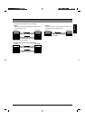
Cover
(Connector side)
0
5
43
2
1
87
96
(Terminal Pin Layout)
Pin 1 of alarm output terminal
(CN24)
Pin 1 of CONTROL terminal
(CN22)
Pin 1 of ALARM I/O terminal
(CN23)
Pin 1 of alarm input terminal
(CN26)
7
6
9
8
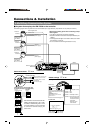
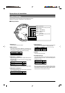
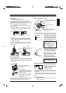
Ⅵ Ceiling Mount
7
[ALARM I/O] Input/Output Terminals (CN23)
Terminals for Alarm input 1 and Alarm output 1.
☞
P. 15
Pin No. Signal Name
1 Alarm output 1
(N.OPEN)
2 Alarm output 1 (COM)
3 Alarm output 1
(N.CLOSE)
4 Alarm input 1
5 GND
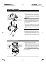
8
[CONTROL] Terminals (CN22)
Connect to a RM-P2580 remote control unit.
Controls, Connectors and Indicators
Pin No. Signal Name Mark
1 TX + A
⅜
2 TX – B
⅜
3 RX + C
⅜
4 RX – D
⅜