


10
Name and Function of Parts
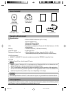
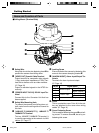
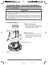
ⅥCeiling Mount (Terminal Side)
Getting Started
1
Safety Wire
Hang this wire to the wire fastening hook & to
prevent the camera from falling down.
2
[VIDEO OUT] Coaxial Cable Terminal
Output terminal for composite video signals
(1 Vp-p and output impedance of 75Ø). Con-
nect this to devices such as video monitors.
(
☞
Page 18)
Output is restricted signals in the NTSC for-
mat only.
3
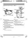
[POWER INPUT DC12V] DC12V Input Ter-
minal
Connect this to the Converter Unit that has
been supplied.
4
Safety Wire Mounting Hole
To prevent the camera from falling down, at-
tach a wire from the ceiling slab or channel to
this hole.
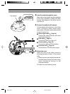
5
[10BASE-T/100BASE-TX] 10BASE-T/
100BASE-TX Terminal
This is a 10BASE-T/100BASE-TX terminal. It
is used for connecting to the network via LAN
cables. (
☞
Page 17)
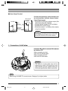
6
Locking Screw
Ensure to fasten the camera by fastening this
screw to the camera clamping bracket #.
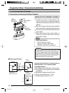
7
[ALARM IN/OUT] Alarm Input/Output Ter-
minals
Ter minals for alarm input and output.
(
☞
Page 16)
8
Cover
This is a protection cover. Cut a slit in the rub-
ber cap attached to the cover when wiring
cables. (
☞
Page 14)
9
Cover Fastening Screw
This is used for fastening the cover 8 and ceil-
ing mount. To remove cover 8, do so by un-
fastening this screw.
7
6
5
2
1
9
3
4
8
Signal Name
Alarm Output
Alarm Input
Alarm Output 1
Alarm Output 2
Alarm Input 1
Alarm Input 2
GND
1
2
3
4
5
Pin No.
C625_p2-24 05.3.4, 8:08 PM10