


15
1
2
3
4
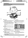
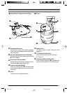
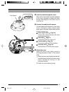
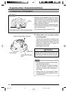
Cap (Upper)
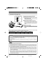
3.
Lead the cable through the cover
Make a slit on the (rubber) cap that is attached
to the cover, followed by leading the cable
through. See diagram on the left on how to
make the slit.
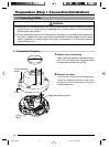
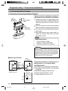
4.
Connect the cable to this camera
Connect cables to the terminal on the ceiling
mount. Connection cables include alarm
signal cable, LAN cable, coaxial cable and that
for the Converter Unit.
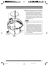
1
Alarm signal cable (
☞
Page 16)
Connect this cable to devices with alarm
input/output terminals.
2
LAN cable (
☞
Page 17)
Connect this cable to a hub or PC.
3
Coaxial cable (
☞
Page 18)
Connect this cable to NTSC monitors.
4
Converter Unit (
☞
Page 19)
Connect this to a DC12V power supply.
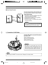
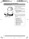
5.
Attach the cover
Attach the cover to the ceiling mount by
following procedure of Step 2 in the reverse
order.
1
Attach the cover upon aligning the hole with
the safety wire mounting hole on the ceiling
mount, followed by turning it in the
clockwise direction.
2
Fasten the cover fastening screw.
C625_p2-24 05.3.4, 6:22 PM15