


16
Preparation (Step 1 Connection/Installation)
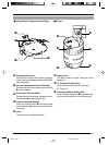
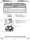
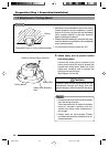
Connect the alarm input/output terminals to
external devices such as sensors and buzzers.
1
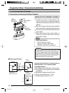
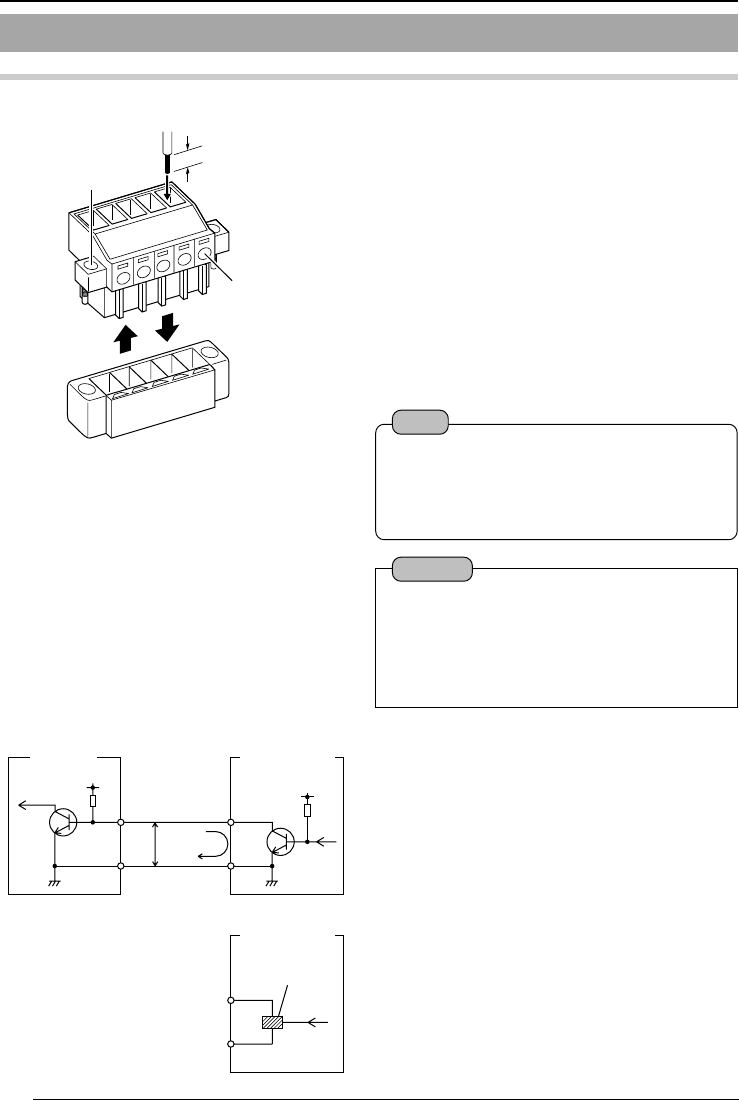
Loosen the screws on both edges of the
terminal block using a flathead screwdriver,
followed by dismantling it as shown in the left
diagram.
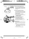
2
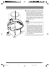
Strip the coating of the alarm signal cable by
about 4mm before inserting it into the terminal.
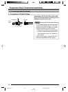
3
Turn the screw on the side to fasten the alarm
signal cable.
4
Upon fastening the alarm signal cable, re-
install the terminal block that has been
dismantled in Step 1.
1-1 Connecting Cables (Continued)
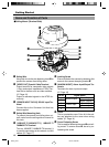
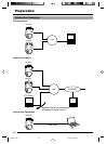
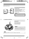
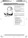
2. Connection to Alarm Input/Output Terminal
Connect this terminal to an infrared, door or
metallic sensor, or to a manual switch.
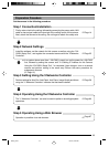
Input Requirements
● No-voltage relay or NPN open collector input
● The polarity of input detection can be selected
via software
● Make/Break/Toggle (at least 250 ms)
● Circuit current at low-level: 1.2 mA
● Voltage applied at high level: 12 V
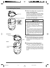
Ⅵ Alarm Input Terminal
4 mm
1
2
3
1
4
OUT
R
DC12V
GND
1.2mA
R
VCC
OUT
GND
12V
Flathead
Screwdriver
Alarm Signal
Cable
Flathead
Screwdriver
VN-C625
Terminal
1 or 2
(Alarm Input
Equivalent Circuit)
Grounding
Terminal
Sensor
Connection
Example (1)
Relay, switch,
etc.
Sensor
Connection
Example (2)
Note
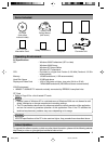
Cable Specifications
50 m or shorter in length
UL1007, UL1015 or equivalent
AWG#22 to AWG#18 or equivalent
Caution
Due to external noise, the cable may not
function properly even when the cable length
is less than 50 m. In this case, use a shielded
cable or take measures such as keeping the
cable away from the noise source.
C625_p2-24 05.3.4, 6:22 PM16