


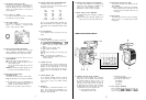
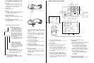
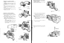
185.
Electronic
Shutter
Selection
Switch
( O F F / 120 / 500 / 1000 /
S S / E L C)
This
switch
is
operative
only
when
a
camera featuring
the
electronic
shutter
function
is
connected
with
this
unit
OFF:
set
this
switch
to
this
position
when
recording
normally with
standard
shutter
speeds
120/500/1000: Choose
the
suitable
shutter
speed
from
these
when recording
high
speed
action.
S/S:
Shutter
speed
can be
adjusted
to
the
desired
position
using
SYNCRO
in
No 1 Sub
Menu
so that
horizontal
bar
noise
will
be
reduced
when
this
switch
is
set
to
this
position
ELC:
The
ELC
position
makes the
electric
control
for
the
luminance
with
the shutter
Notes:
1. The
smear
may be appeared
with
the
high light
l ght
objects
2. When the
Lens
Iris
Selection
Switch (186) has
been
set
to
the AUTO,
the
fine
adjustment
of
Electronic
Light
Control
(ELC)
and
lens
iris
can
be
made by
the
Iris
Level
Control (187)
simultane-
ously
186.
Lens
Iris Selection Switch (IRIS,
MANU/AUTO)
AUTO: When the
iris
Control Selection Switch of the
lens
has
been
set
to
the A (Auto)
position,
the iris
level
of
the
lens
is
controlled
automatically
When AUTO IRIS
in
No.1 Sub
Menu
has
been
set
to ADJ
ON.
the
iris
level
can be
adjusted
fine
by
means
of
the
Iris
Level
Control (167)
MANU:
The
iris
level
of the
lens
is
controlled
manually
by
turning
the
Iris
Level
Control (167)
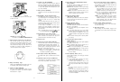
187.
Iris
Level
Control (IRIS
LEVEL)
This
control
is
used
to
adjust
the
lens
iris
level.
The
iris
level,
which
had
been
automatically
set, can be
con-
trolled
fine by
using
this
control when the
Lens
Iris
Selection
Switch
(166)
is
set
to
the
AUTO
position
and
AUTO IRIS in No.1 Sub
Menu
is
set
to
the ADJ
ON
position
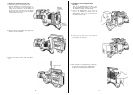
188.
Down Switch (DOWN)
This
Switch
is
used
to
decrease
the set value of
the
item
pointed out
by the cursor
in
a
menu
189.
Up
Switch (UP)
This
switch
is
used
to
lncrease
the set
value
of
the
desired
item
pointed
out
by the cursor
in
a
menu
190.
Item Switch
(ITEM)
This
switch
is
used
to
choose
the
item
in
the set-up
menus
191.
Page
Switch (PAGE)
This swltch
is
used to
select
the
desired
set-up
menu
from
the avallable
menus
- 26 -
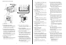
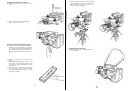
192.
User
Set Switch
( OFF / 1 / 2 )
This
switch
selects
Encoder
output
or
EVF (black and
white)
output
from
the
Video
Output Connector and
whether
the
User
Set
Function
is
avallable
as
follows:
OFF:
Switch
set to
position
OFF
Setup
function
is
not
available
1: Switch set
to
position
#1
User
Set
function
is
available
and the
User
Set
Menu
is
displayed
on
the EVF
2:
Switch
set
to
position
#2:
User
Set
function
is
avallable and the
User
Set
Menu
is
displayed
on
the
monitor
and the EVF
193. Chroma
Gain
Fine Control (ADJUST CHROMA)
This
control
allows
for
fine
adjustment
of the
chroma
signal
level
for
matching
the
chroma
levels
of
all
the
cameras
in
a
system
Adjust
this
Control
only
after
having
set the Cable
Length
Compensation
Switch (195) and
the
Luminance
Gain
Fine
Control (194)
to
the
correct
posi-
tion
194. Luminance Gain Fine Control (ADJUST
Y
)
This
control
allows
for fine
adjustment
of the
lumi-
nance
signal
level
for
matching
the
levels
of
all
cam-
eras
in
a
system.
Adjust
thls
control
only
after
having
set the Cable Length
Compensation
Switch
(195) to
the
correct
position
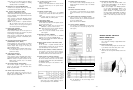
195. Cable Length
Compensation
Switch
(COARSE,
1/2/3/4)
This
switch
is
used
to
compensate
for
extensive
cable
length
used
with
the
26-pin
studio
cable
between
this
unit
and the camera.
1.
Use
for
cable
length
of
less
than
75m
(225
ft)
2
Use for cable
length
of
75-150m
(225-450
ft)
3
Use for cable
length
of
150-230m
(450-690
ft)
4.
Use for cable
length
of
230-300m
(690.900
ft)
199. Subcarrier Phase Fine Control for Gen-lock
(SC FINE)
This
control
allows
for
adjustment
of
the camera
signal
subcarrier
phase
from
0º
to
360º
to
match the phase
with
that of the
burst
signal
at
the Gen-lock
Input
Connector
in
a
system
configuration
197. Subcarrier Phase Coarse Control for Gen-lock
(SC COARSE)
The
Coarse
control
adjusts
the
subcamer
phase from
0”
to
360”
in
90º
steps,
while
Fine control
allows
for
continuous
fine
adiustment
over
a
range
of
90
198. Horizontal Phase Control for Gen-lock (H PHASE)
The
horizontal
phase
of the camera
signal
can be
adjusted
to
match
the
horizontal
phase of the signal at
at
the Gen-lock
Input
Connector
199. Intercom
Level
Control
(INTERCOM
LEVEL)
Use
this
control
to
adjust
the
volume
level
in
the
head-
set
connected
t
o
the
Intercom
Jack
200.
Intercom
Jack
(INTERCOM)
This jack is used
for
communications
between
the
camera
operator
and
the
Remote
Control
unit
opera-
tor
in
a
system
configuration
with
a
Special
Effects
Generator
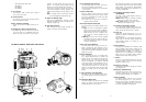
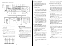
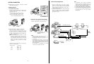
201.
Camera
Connector (CAMERA)
This
Connector
is
connected
with
the
VTR/RCU
Connector of camera by
using
26-pin
studlo
cable.
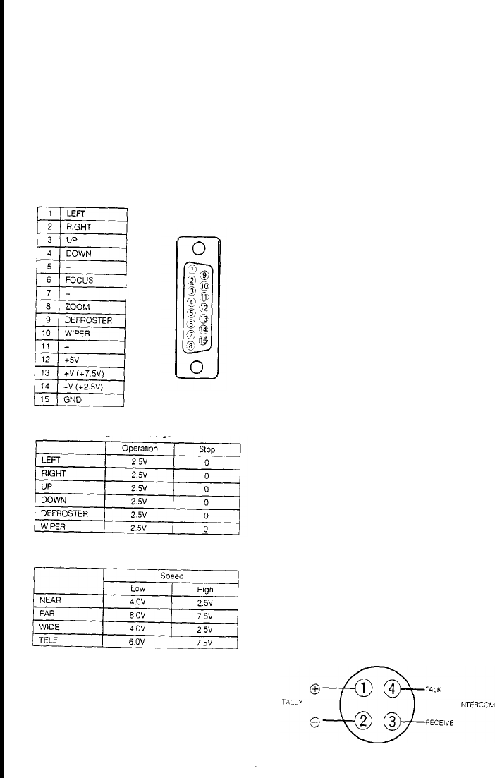
202.
Control
Connector
(CONTROL IN)
This
connector
is
connected
with
the control
connec-
tor
of the
pan/tilt
unit
or
lens
control by
using
the
15-
pin
multi
cable.
Pan/Tilt
or
Housing
Control
Voltage
Lens
Control
Voltage
Note:
The impedance
for
the
control
voltage circuit
should
be 2 kOhms
or
less
203.
Gen-lock
Connectors
(GEN-LOCK
IN/OUT/AUTO
75 Ohm. - Hi Z)
These
Connectors
receive
the
gen-lock
signal
(black
burst)
or
composite
from the
Special
Effects
Generator
for
system
reference
When
connecting
two
coaxial
cables
with
BNC
con-
nectors
to
these
connectors,
the
high
impedance
video
loop
is
automatically
selected.
At
all
other
times,
these
connectors
are
automatically
terminated
with
75
ohms
Note: When
not
looping
the
gen-lock
signal,
be
sure
to
connect
the
coaxial
cable to
the
GEN-LOCK IN
Connector o
therwise
these
connectors
can
not
be
automatically
termlnated
204.
Auxiliary
Input
Connectors
(AUX
IN/OUT/AUTO
7.5 Ohm. / Hi-Z )
These
Connectors
receive
the
lineview
signal
from
a
Special
Effects
Generator
Two
connectors
are
provid-
ed
for
bridging
or
looping
application
When
connecting
a
single
coaxial cable
with
BNC
connector
to
this
connector,
these
connectors
can
not
be
automatically
terminated
with
75 ohms
Note:
When
not
looping
Aux.
signal,
be
sure
to
con-
nect
the
coaxial
cable
to
AUX IN
Connector.
Otherwise,
these
connectors
are
automatically
terminated
with 75 ohms
205. Video Output Connectors (VIDEO 1, VIDEO 2)
These
connectors
supply
a
composite
video
signal
to
a
Special
Effects
Generator,
a
Video
Monitor
or
a
VTR
206. S-video Output Connector (S-VIDEO
OUT)
This
connector
outputs
the
Y/C
signal
when
the
Camera Output
Signal
Selector
is
set
to
Y/C
position
207. Audio Output Jack (AUDI0
OUT)
By
setting
the
Audio
Level
Selection
Switch
of
the
Camera
Adaptor
AW-AD700BSE
to
the -20
dB
posi-
tion,
the
audio
output
is
avallable
Note: In case of
Multiplex
or
VP
Multiplex
operation
set the
Audio
Level
Selection
Switch
of
the
Camera Adaptor
AW-AD700BSE
to
the -20
dB
position,
the Switch 1
on
the
Audio
Board
ins
ide
the Camera
Adaptor
AW-AD700BSE
and
Switch
2
on
the MOD board
inside
this
unit
to
the AUDI0
position
for the
Audio
Output
function
to
be
acti-
vated
208.
Tally
and
Intercom
Input
Connector
(TALLY
&
INTERCOM)
This
connector
is
connected
with
the
Tally/Incom
con-
nector of
a Special effect generator
Generatcr