


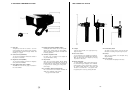
?? 26
pin
Studio
Cable
(RCU
Cable)
WV-CA26U15
WV-CA26U30
WV-CA26U100
80
.
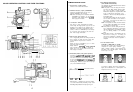
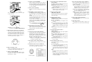
Lens
Connector
Thi
s
connector is
used
to
connect the le
ns
cable
for
zoom,
focus
or
servo
control.
81. C
ontrol
connector
This
connector is
used
to
connect the optional Pan/T
ilt
Control Cable
WV-CA10U25
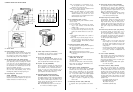
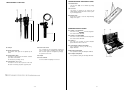
92.
Battery
Connector (BATTERY)
Connect the
cord
from the Battery
Pack
t
o
this
con-
nector
93.
Recording/Tally
Indicator
(red)
(REC
TALLY)
This
i
ndicator
Iights
when the
VTR
is set
to
the
record-
ing
mode (through the
VTR
Start/Stop
Button) and
informs the p
erson
concerned
of scenes being
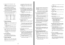
14X SERVO CONTROL ZOOM LENS AW-LZ14ST73
recorded.
The
Tally
indicator
also
lights when the
camera is
in
full
system operation together
with
the
Remote
Control
Unit
and
Special
Effects Generator i
n
case
a
tape
is
not loaded
or
the tape end is reached,
or if
the
servo
mechanism
is
working
i
mproperly,
this
indicator
will start
blinking
to
warn the
operator
of
such
faults.
Note:
lf
a
portable
VTR is not connected to the cam-
era, the
Recording/Tally
indicator will not light.
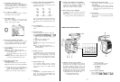
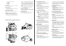
84.
Battery
Pack
Mounting
Angle
Mount the
AC
Adaptor/Charger
WV-PS34
or
Power
Separator
WV-PS700
on
the camera by
sliding
i
t
down
along
this
mounting
angle
85.
66-pin
Multi Connector
When
mounting
this
adaptor
engage
the
66-pin
con-
nectors
on
the camera and
this
connector
94-
-16 -
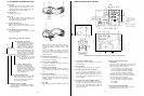
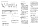
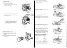
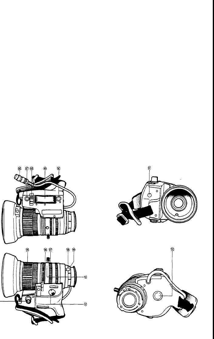
86.
Le
ns
Cable with
12-pin
Connector
This cable s
upplies
power
to
the
servo
control
zoom
motor and the
automatlc
iris
control
device.
The cable
should
be connected
to
the
Lens
Connector
(1)
on
the camera.
87.
Auto Iris Button (IRIS)
When
this
button
is
pressed
while
the
lris
Control
Selection
Switch (86) is set
to
the M (manual) position
t
he
Iens
iris is
automatlcally set
according
to
the
light
intensity
reaching
the
lens
Note: Button must be pressed
for
5
seconds
or
improper iris
setting
will
result
88.
Iris Control
Selection
Switch (A/M)
This
switch
selects
the
operational
condition of the
lens iris:
A (Auto): The
lens
iris is
automatically
controlled.
When the camera is
used in
studto
applications
together
with
the
Remote
Control
Unit
(RCU), this
switch
should
be set
to
the
‘A’
position. In this
case, the
lens
iris is remotely
controlled
from the
RCU
or
RCB
M
(Manual): The
lens
iris can be manually
controlled
by
rotatlng
the
lris
Rlng
(97).
With
this
setting, the
correct
lens iris
setting
can
also
be set by
press-
ing
the Auto
Iris
Button (87).
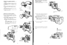
89. Servo
Zoom
Control
(Wide/Tele)
The
zoom
function
of
this
1.4f
zoom
lens
can be
con-
trolled
by
pressing
this
control.
Zooming
to tele as
well
as
wide
angle is
possible.
Furthermore, the
zoom-
i
ng
speed
can be
controlled
by
changing
the
pressure
applied
on
this
control.
90.
Return
Video Button
When
an
auxlllary
signal
such
as a
Ilneview
signal
from a
Special
Effects Generator is supplied to the
auxiliary
connector of the
Remote
Control
Unit
(RCU)
while
the camera is set up for system operatlon,
this
signal
can be
previewed
on
the
electronic
viewfinder
as
long
as
this
button is kept pressed. When a
3/4"
U-
vision
portable
recorder,
connected through the
VTR
s
14-pin
camera i
nput
connector,
or
an
S-VHS
VTR
recorder
is
set
to
the playback
mode,
the played
back
picture
can be
viewed
as
long
as
this
button is
kept
pressed
91. Auto Iris Sensitivity Control (IRIS GAIN)
With
setting
the iris Control
Selection
Swltch
(88)
to
the A
position,
adjust
the iris
Galn
by
turnlng
this con-
trol.
92.
VTR
Start/Stop
Button (VTR)
This
switch
is
used
to start and pause the
connected
recorder.
The
function
of
thls
button is i
dentlcal
t
o
the
VTR
Start/Stop
Button (5)
on
the camera
-17 -
After
having
set the
recorder
to the
recording
standby
mode,
pr
ess
this
button
to
start and pause
recording.
While
recording
is in
progress, the Recording/Tally
indicator
in the
viewfinder
and the
Tally
Light
(101)
on
front of the
viewfinder
lights.
93.
Servo/Manual
ZOom
Selection
Switch
(SERVO/MANU)
This
swltch
is
used
to
select
between
zooming by
servo
control or
manually
SERVO:
Zoom
operation is performed by
pressing
either
side
of the
Servo
Zoom Control (89)
MANU:
Zoom
operation is
performed
manually
by
rotating
the Zoom
Ring/Lever
(96)
94. Connector
for
Zoom
Remote
Controller
The Zoom
Remote
Controller
i
ncluded in
the
Lens
Control
Kit
WV-LK35
should
be connected
to
thls
con-
nector.
This
will
allow
remote
control
of
zooming
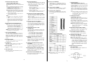
95.
Focus
Ring
Rotating
this
ring will
I
change the
lens
focus.
By
observing
the
picture
in
the
vliwfinder,
correct
focus
can
easily
be set.
With the
optlonal
Lens
Control
Kit
WV-LK35, i
ncluding
flexible cable for the
Zoom
Remote
Controller
and
Focus
Controller,
zooming
and
focusing
can be
remotely
controlled.
96. Zoom
Ring/Lever
By
seyying
the
Servo/Manual
Zoom
Selection
Switch
(93)
to
the
MANU
(manual) position,
zooming
can be
manually
performed
through use of
this
rlng/lever.
13
times
magniflcation is
posslble
from
wide
angle
to
telephoto.
When the
Servo/Manual
Zoom
Selection
Switch
(93) is set
to
the SERVO
position,
zooming is
performed
with
the
Servo
Zoom Control
(69)
97. Iris
Ring
When the iris Control
Selection
Switch (66) is set to the
M (manual)
positlon,
the
lens iris
can be
manually
adjusted by
rotating
this
ring.
98.
Flange-back
Lock
Knob
The
Flange-back
Adjustment
Ring
(99) can be locked
by
turning
this
knob.
99.
Flange-back
Adjustment Ring
The
flange-back
(or
back
focus) of the
lens
can be
adfusted by
rotating
this
ring.
The
Flange-back
Lock
Knob (98)
should
be
released
prior
to
adjustment
100.
Macro
Ring/Button
For
close-up
shooting,
rotate
this
ring
to
the
macro
area
while
pressing
this
button. After
setting
lhe
Servo
Zoom Control
(69)
to
the WIDE
position,
close-
up
shooting
up
to
approximately
50 mm
(2”)
from
the
lens
surface
is
posslble
by
rotating
this
ring