


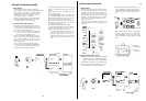

F. VP Multìplex
SyStem
CONTROL
Precaution
In gen-lock
operatlon
in
a
video
power
(VP)
multiplex
system
with
a
single
coaxial
cable,
the
camera may
become
out
of
syn-
chronizatlon
depending
on
the
waveform
distortion
of the
burst
signal
that
serves
as a gen-lock
signal
-
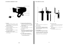
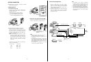
Connect the
Multiplex
Output Cable
on
the
WV-PS700
lo
the
Multipiex
Slgnal
Connector
on
the
AW-AD700BSE.
- Connect the Power Cable
on
the
optional
Power Separator
WV-PS700
to
the
External
DC
Input
Connector
on
the
AW-
AD700BSE
- Connect the
coaxial
cable between the
Multiplex
Input
Connector
on
the Power Separator
WV-PS700
and the
Multiplex
Connector
on
the RCU
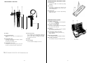
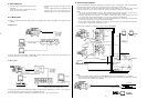
- To
control
the Zoom
or
f
ocus
function
of
lens,
connect the Control Cable
on
the
lens
having
the
Focus
or
Zoom
function
to
the
Lens
Connector
on
AW-AD700BSE.
And
then
connect the
multicable
between
the WV-RC700A and
lens
control
unit
Notes:
1
The
optional
Power Separator WV-PS700 and the Camera Adaptor
AW-AD700BSE
are
required
to
supply
the power
to
the
camera from
this
unit
2
The
optional
studlo
cable
(26-pin)
cannot be
used
i
n
the
VP multiplex system simultaneously
slmuitaneously
3
In
this
system, R
/G/B.
Y/C, Y/PR/PB
and
Aux
cannot be
supplied.
4
Be
sure
to
set
the
Cable
Selection
Swltch
on
the Camera Adaptor
AW-AD700BSE
to
the MPX
position
and the Cable
Selection
Switch
on
the RCU
to
the VP
positlon.
5.
After
turning
on
the power
of
this
unit
and camera
head,
it
takes
approxlmately
8
seconds
to
control the camera
6
When
the
Camera Adaptor AW-AD700BSE
is
used
in
the
above
system, the
following
items
are
not
available
a.
Bidirectional
I
nter
Communication
b.
Audio
Output
c. Zoom,
or
Focus Control
d.
Pan/Tilt
Control
7
Pan/Tilt
Control
SIgnaI
Input
to
the Control
Connector
on
the RCU
is
output
from Control Connector
on
AW-AD700BSE.
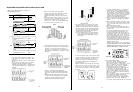
8.
For the
Audio
function,
set the
Switch
2
on
the
MOD
board
Inside
this
unit
as
shown
below
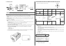
- 44 -
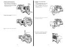
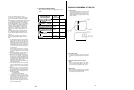
OPERATING
PROCEDURE FOR CAMERA RECORDER
APPLICATION
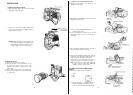
1.
Turn
on
the
Power
Switches
on
the camera and
VTR.
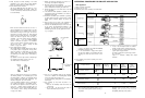
DC POWER
Operating
mode
of
Operating
mode
of
Power
Switch
Power Indlcator
Dockable
VTR/
Portable VTR
Dperatlng
mode of
Sub-VTR
camera
(SAVE
is
bullt-in)
VTR
CAM
Power
Operating
condltlon
OFF
lights
off
Power off
VTR:
|l
The tape
loadlng
The tape
SAVE
ON lights red
The power
af
VTR
The
recording
and camera are
power
on
mode
is
controlled
turned
on
by the
VTR
Start/
stop
Button.
Notes:
1
When the power of the camera
is
turned
off from
on,
the sub-VTR
is
put
in
the
recording
stop
mode from the
recording
start/stop
mode
Then the recording
Start/Stop
is
controlled
the
operating
switch
on
the VTR
When the power of the camera
is
turned
on
from off, the
recordlng
is
stopped by
setting
the
operating
switch
on
the VTR
to
the
recording
start
mode
Then the recording
start/stop
mode
is
controlled
by the
VTR
Start/Stop
Button
on
the camera.
2
When
pressing
the
VTR
Start/Stop
Button
after
setting
the
Dockable
VTR
to
ON
--->
SAVE -->ON,
the
recordlng
start/stop
mode
is
reversed.
3
When
turnlng
off
the power of the
AU-45H
in
the camera
recorder
system. the power off control from the camera
side
is
not
avallable.
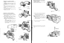
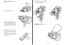
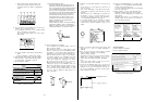
2.
Insert
a
cassette
in
the
VTR
3.
Set the
switches
on
the camera as
follows:
Switches
Positions
Note: Set
these
switches
to
the
most
suitable
position
according
to
shooting
condltions
- 45 -