


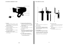
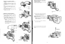
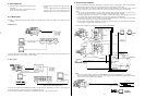

C. Studio Application
1
Connection
with the
Remote
Control
Unlt
by the
26-pin
multi-cable
Connect
the
26-pin
studio
cable
between
the
camera
and
the
Remote
Control
Unit
(RCU)
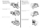
2
Connection
with
the
Remote
Control
Unit
by the
coaxi-
al cable
Connect a
coaxial
cable between the
Multiplex
Signal
Connector
(50)
on
the Camera Adaptor and the
Multiplex
Connector (151)
on
the
Remote
Control Unit.
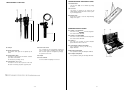
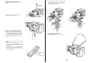
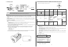
D. PC Mode System
Precaution:
The specified software
should
be
requlred
for
this
operatlon.
Please
contact
with
qualifled
service
personnel
for
this
operatlon.
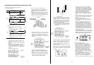
PC Mode System 1
Connect the WV-CA10B02, WV-CA10625
or
WV-CA10B50
10/10-pin
cable between the
Remote
Control
Box
Connector (37)
on
this
camera and Camera 1 Input Connector
on
the WJ-PC500
PC
Mode
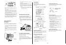
System 2
Connect
the
WV-CA10B02,
WV-CA10B25
or
WV-CA10B50
10/10-pin
conversion
cable
between
the
Camera 1 Input Connector
on
this
unit
and the
Remote
Control
Box
Connector
on
the
Remote
Control
Unit.
Connect
the
25/9-pin
converslon
cable between the
RS-232C/422
Connector
on
thls
unlt
and the computer
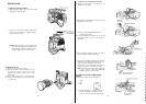
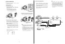
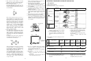
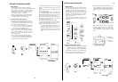
E.
Gen-lock Studio Application
- Connect
a
coaxlal
cable for the
gen-lock
signal
between the black burst output
on
the
productlon
system and
Gen-lock input
Connectors (143)
or
(203)
on
the RCU. (The
signal
may be bridged
or
looped through
to
another RCU.)
- Connect the
coaxial
cable for the
lineview
signal
between the effect output
connector
on
the
production
system and the
Auxiliary
Input Connector (144)
or
(204)
on
the RCU. (The
signal
may be bridged
or
looped through
to
another RCU
)
Notes:
1. The
Tally
light
and
Intercom
between
the camera, RCU and
Speclal
Effects
Generator
will
function
only when
the
4-pin
cable for the
Tally
Iight
and
Intercom
is
connected between the RCU and
Speclal
Effects
Generator.
2. The
26-pin
studlo
cable can be extended
up
to
a
maxlmum
of
approx
300m
(1000
ft). When
extending
the cable,
be
sure
to
Set the Cable Length
Compensation
Switch
(115) t
o
the
position
matching
the
extension lenght
3. The
Subcarrier
Phase
Coarse
and
Fine
Controls
(139) and the
Horizontal
Phase Control
(138)
or
(198)
on
the RCU
should
be set
to
match other cameras i
n
the system.
Refer to page 54 for details.
lo
etalls.
4. B
e
sure
t
o
Set the Cable
Selection
Switches
(73)
on
the Camera Adaptor and (152) or (201)
on
the
Remote
Control
Unit to
MULTI
positlon,
i
f
using
the
26-pin
multicores
studio
cable
- The MPX mode
is
avaliable
when
connecting
the Camera Adaptor
AW-AD700BSE
G/L
OUT
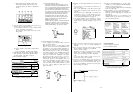
Notes:
1
2.
When
using
the MPX
mode
by
connecting
the
AW-AD700BSE,
INCOM.
AUX and
R/G/B
outputs
are
not
functoned
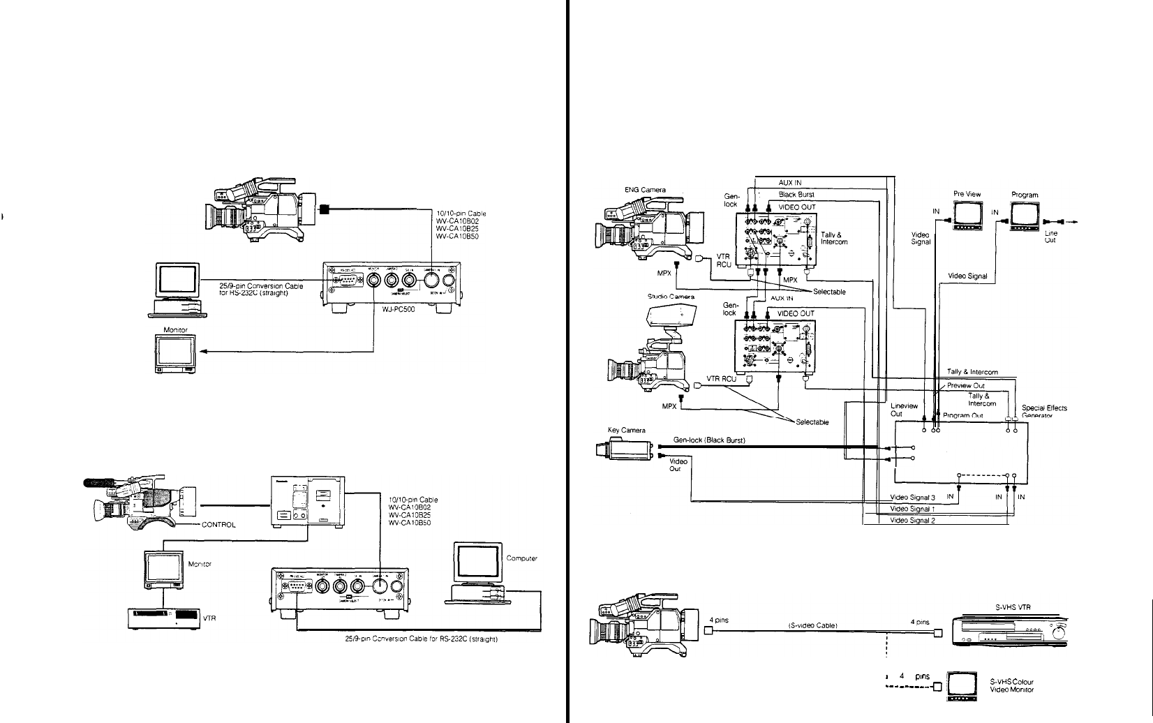
When the
Colour
Camera
AW-F575E
is
connected
to
a desk-top type S-VHS
VTR
or
directly
to
the
video
monitor
for S-VHS
format, the S-VHS cable
(S-vldeo
cable)
is
required.
- 43 -