


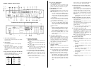
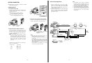
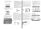

SYSTEM CONNECTION
CAUTION:
Keep
the
power
switches
of
all
units
in
the
OFF
position
during
connections.
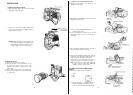
A. ENG Application
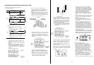
1. Connection with the VTR
Connect the
VTR
cable
between
the camera and the
Panasonic
portable
colour
VTR
(The standard
VTR
cable length
is
3 m.
(10
ft).
Portable
VTR
wlth
14-pin
camera connector
VTR
cable
WV-CA26A/14
(26P-14P
cable)
Portable
VTR
wth
26-pin
camera connector
VTR
cable
WV-CA26A/26
(26P-26P
cable)
2. Connection with the Remote Control
Box
Connect the
Remote
Control
Box
Connector (37)
on
the Camera Head
to
the
Remote
Control
Unit
Extension
Connector (156)
on
the
Remote
Control
Box
by
using
the
optional
RCB Cable
WV-CA10B02,
WV-
CA10B25
or
WV-CA10B50
Note: In the
following
system
connection,
the
video
signal
from the
Monitor
Output Connector (36)
on
the Camera Head has
priority
of the video
signal
over
the
Monitor
Output Connector (154)
on
the
Remote
Control Box, so the
ptcture
is
not
dis-
played
on
the monitor connected
to
the
Remote
Control Box
The
decrement
of the
video
signal
for the cable length
is
shown
in
the
following table
The cable length
Decrement
2 m.
Approx. 10%
25 m.
Approx. 15%
50
m.
Approx. 20%
100 m.
Approx. 30%
- 40 -
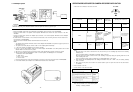
3. Connection with a
sub-VTR
(back-up
VTR)
Connect the
sub-VTR’s
camera connector
to
the
Camera’s
10-pin
Remote
Control
Box
Connector
Notes:
1
Only
video
slgnal,
audio
signal
(-20
dB)
and
start/stop
signal
are
sent
to
the
sub-VTR
2. The
extension
cable length for
the
sub-VTR
is
up
to
10m
(30
ft).
3
In the
above
system
connectlon,
the vi
deo
signal
from the Monitor Output
Connec!or
(36)
on
the
Camera
Head
takes
priority
over
the
vldeo
sIgnaI
from the
Monttor
Output
Conector
(154)
on
the
Remote
Control
Box
So, the
picture
is
not
displayed
on
the
monitor
connected
to
the
Remote
Control
Box.
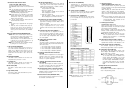
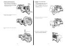
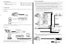
B.
Gen-lock
EFP
Application
1
Connect a
coaxial
cable for the gen-lock
signal
between
the Gen-lock
Input
Connector (51)
(BNC-
type)
on
the Camera Adaptor and the Black
Burst
Output
Conneclor
on
the
production
system,
such
as
the
Special
Effects
Generator.
2
Connect
the
coaxlal
cable for the
vldeo
output
siIgnaI
between
the
Monitor
Output Connector (36)
(BNC-
type)
on
the camera and the Video
Input
Connector
on
the
production
system.
ENG Camera
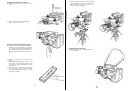
Notes:
1 The
Subcarrier
Phase
Coarse
and
Subcarrier
Phase
Flne
as
well
as the
Horzontal
Phase
on
the
camera should be set
to
match the other cameras
in
the system
Refer
to
page
49 for
details
2.
Refer
lo
the
operatlng
nstructlons
accompanylng
the
Speclal
Effects
Generator
for
further
detalls.
3 Do
not
connect
the coaxial cable for the gen-lock
signa1
to
the Gen-lock
Input
Connectors
(51)
on
the Camera Head and
on
the Camera Adaptor
slmultaneously.
PREVIEW
PROGRAM
BLACK
BURST
(GEN-LOCK)
ENG Camera
-
;
BLACK BURST (GEN-LOCK)
-pp
BLACK
BURST
VIDEO OUT
VIDEO
INPUT
VIDEO
VIDEO
OUT
- 41 -