


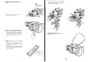
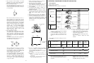

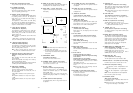
11. Co
nfirm
the f
lange-back
adjustment on the
lens
as fo
l-
Iows.
-
Aim
the camera at a dark object more
than
2m
(6 f.
)
from
the camera.
-
Zoom in
(from
wide-angle
to tele) with the Zoom
Rlng/Lever
(96)
or
the Servo Zoom Control (222)
or
(235) of the
Lens
Control
Kit,
and
adjust
the
lens
focus
with
the Focus
Ring
(95)
or
the Focus
Controller
(226)
or
(237) of the
Lens
Control
Kit
- Zoom out
(from
tele
to
wde-angle)
and
confirm
that
the
picture is in focus
s.
If
not,
the flange-back of the
lens
should be adjusted
according
to
the
Instructions
‘in 'Lens
Flange-back
Adjustmen'
on
page 54
12. Zoom
in/out until
the
desired
composition is
achieved
Focus the
lens
until
the object
is
i
n
Sharp focus by
watching
the picture in the
vlewfinder
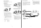
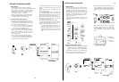
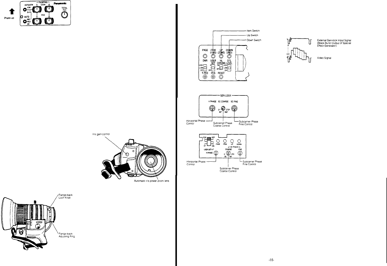
LENS
FLANGE-BACK
ADJUSTMENT
If
the flange-back is not adjusted correctly, correct focus-
ing
cannot
be
mantained
through the
entire
zoom
range.
- Aim
the camera at a dark
object
more than 2m (6
ft)
away from the camera and
loosen
the
Flange-back
Lock
Knob (96)
- Zoom
in
(from
wide-angle
to tele)
wih
the
Servo
Zoom
Control (69) and adjust the
lens
focus with the Focus
Ring
(95)
- Zoom
out
(from
tele to
wlde-angle)
and adjust the
focus by
turning
the
Flange-back
Adjustment
Ring
(99).
- 54 -
- Zoom in
again
and adjust the focus by
turning
the
Focus Ring
- Newly, zoom
ouf
and, i
f
necessary,
adjust
the
focus
wih
the
Flange-back
Adjustment
Ring.
- Repeat
this
process
until
correct
focus is
malntalnad
throughout the
entire
zoom
range When
the
adlust-
ment has
been
completed, tighten the
Flange-back
Lock
Knob.
---- Once the flange-back of the
zoom
lens
has
been
adjusted, no
further
adjustment is necessary
unless
the
lens
is
changed.
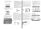
IRIS GAIN CONTROL IN A
LENS
An iris
gain
control
hole is
usually
provided in th
e front
of
a
lens. Adjustment of the iris gain, with a screwdriver
through the
hole
may be done as
follows: (
Shape and
location
of the hole may
vary
depending
on
the
lens
make.)
1 Turn
the iris
selection
switch
to
Position
A (AUTO).
2
Rotate
the iris
gain
control
to
the
maximum
galn
but in
a
r
ange
where
no
hunting
or
oscillating
of the irirs ring
develops.
AUTOMATIC IRIS ADJUSTMENT
When i
nstall
or
change
the
lens,
automatlc
iris adjustment
should be done
before
operation.
Refer
to
page 17 for the
details
-
Automatic
iris
adjustment
when
lens
is
changed
Turn
power
on
while
pressing
the
item
(ITEM/AWC)
switch.
The l
ens iris
is
automatically
opened
and
closed
for
auto-
matic
iris
adjustment. It will
be completed in
around
30
seconds
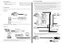
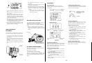
ADJUSTMENT
Gen-lock
Adjustment
When
using one or m
ore
cameras
in
a system
which
includes
a
special
effect
generator
,a gen-lock adjust-
ment is required.
Camera Head
Remote Control Unit
Horizontal Phase Adjustment
This
should be
adjusted
so that the phase of the
horizontal
blanking
of the
colour
bar
signal
from the camera matches
that from the Special Effects
Generator
by
adjustment
with
elther
the camera
or
RCU
(RB)
Controls
Adjustment
with the Camera Controls:
1
Set the
Scene
Flle
Selectlon
Swtch
(10)
to the
positlon
1, 2 or 3
2
Set the
Colour
Bar/Night
Eye/Camera
Selectlon
Switch
(27) to
the
BAR
position
3
Set the
User
Set
Switch
(16)
to
the
positlon
1
Note: When
Setting
this
switch
to
the
position
2.
black
and
whlte
video
signal
is
output.
4
Move
the cursor
onto
the H PHASE by
using
the
item
Switch
(14)
5
Adfust
the
Horizontal
Phase by
using
the
Up
(15)/
Down
(16)
Switch
Adjustment with
RCU
(RCB)
Controls:
The
horizontal
phase of the camera
signal
can be
adjusted
by
using
the
Horizontal
Phase Control for Gen-lock (138)
Inside
the
side
cover
of RCU
(RCB)
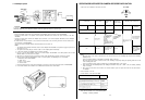
Colour Phase Adjustment
This
should be
adjusted
so that the
colours
of
the
colour
bars
from the camera are
simllar
to
the
colours
af
the
colour
bars
generated
by the
Special
Effects
Generator
Adjustment
with
Camera Controls:
1.
Set the
Scene
Flle
Selectlon
Switch
(10) t
o
the
position
1, 2 or 3
2. S
et the
Colour
Bar/Night
Eye/Camera
Selection
Switch
(27)
to
the BAR
position
3. S
et the
User
Set
Swich
(18)
to
the
position
1
Note: When
Settlng
this
switch
to
the
position
2,
black
and
white
video
signal is
output.
4.
Move
the cursor
onto
the SC COARSE
positlon
by
using
the i
tem
Switch
(14).
5.
The
Subcamer
Coarse
Control can be made by
using
the
Up
(15) and
Down
(16)
Swich.
6.
Move
the cursor onto
the
SC FINE
position
by
using
the i
tem
Switch (14)
7.
The
Subcarrier
Fine
Control can be made by
using
the
Up
(15) and
Down
(16)
Switch
Adjustment
with RCU
(RCB)
Controls:
The
Colour
phase
of
the camera
signal
can be
adjusted
by
using
the SC
Phase
Controls
for Gen-lock (139)
or
(197)
inside
the
side
over
of
RCU (RCB)