


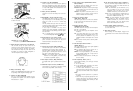
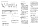
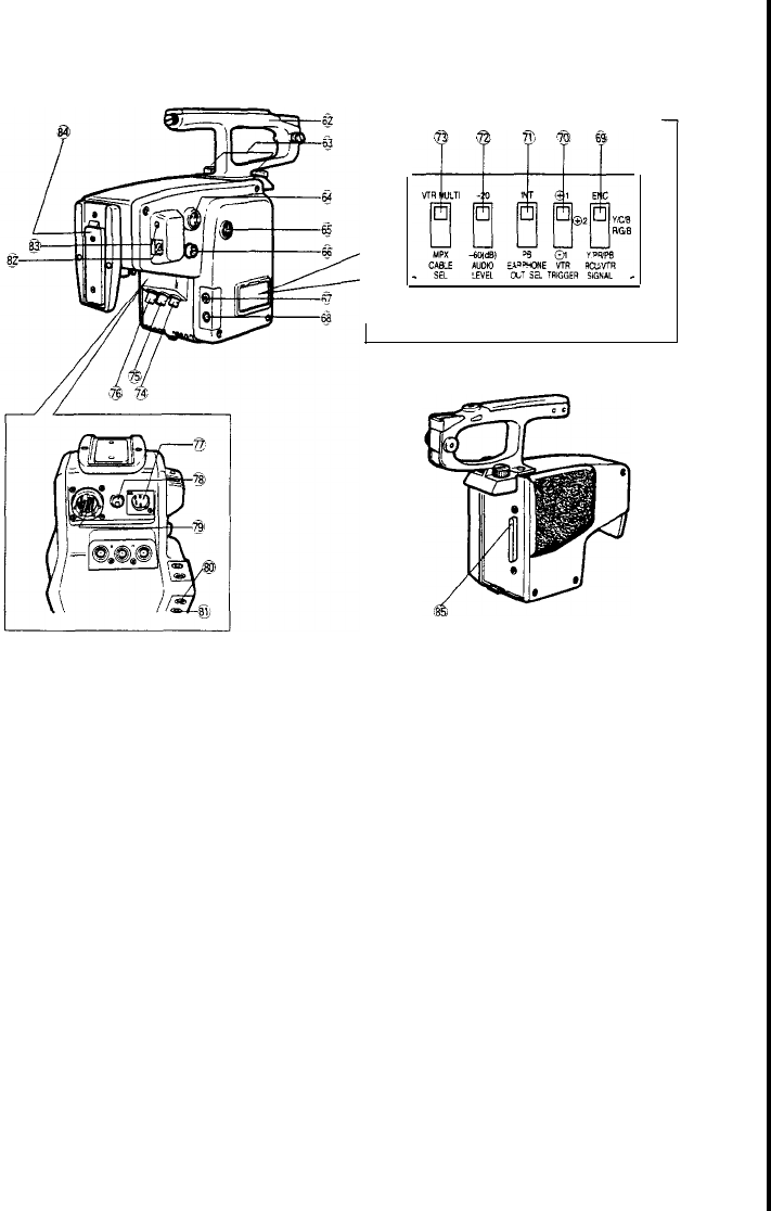
CAMERA ADAPTOR
AW-AD700BSE
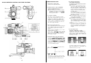
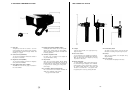
62. Camera
Handle
63. Camera Adaptor
Holding
Screw/Knob
The camera
adaptor
can be removed from the camera
after
loosening
two
knobs
on
top of the
adaptor
and
then
pressing
the
release
button
underneath
of
the
camera
while
pulling
on
rear
of camera
adaptor
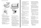
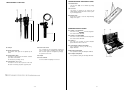
64.
VTR
Start/Stop
Button
(VTR)
(parallel
operation)
This
button is
used
to
change
the recorder mode from
pause
(Recording
Pause) to recording and
functlons
in
the
same
way
as the VTR
Start/Stop
Button
on
the
lens.
Press
once
to
start
recording.
While
recording,
the
Tally
Indicator
in the
viewfinder
Iights
and the
Tally
Light
on
the
vlewfinder
also
lights
When t
he
button is pressed once more,
the
recorder is
set
to
the Pause mode
(Recording
Pause), and the
Recording/Tally
I
ndicator
and
Tally
Light
will go off
65.
Intercom/Earphone
Level
Control
(INCOM
EARPHONE)
Use
thls
control
to
freely
adlust
the
volume
level
in
the
earphone
connected
to
the Earphone
Jack
(68)
or
the
headset connected
to
the Intercom
Jack
(67)
-
14 -
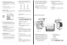
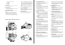
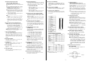
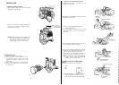
F
66. S-Video Output
Connector
(S-VIDEO
OUT)
The
lumlnance
(Y)
and
chroma
(C)
signals
for S-VHS
VTR
or
monitor
are
provided
at
this
connector
67.
Intercom
Jack
(M6)
(INCOM)
This j
ack
is
used
for
communication
between
the cam-
era
operator
and
operators
of the
Remote
Control
Unit
(RCU)
and
Special
Effect
Generator
in the
system.
68. Earphone
Jack
(M3)
(EARPHONE)
When
an
earphone
is
connected, the
sound
picked
up
by the microphone
or
the
played
back
audio
from
a
3/4"
U-VISION
recorder, connected
to
the camera
through the
VTR
14-pin,
camera
connector,
can be
monitored
Selection
of
the
audio
source is
enabled
by the Earphone Out
Selection
Switch
(71)
69.
RCU/VTR Signal Selection Switch
(RCU/VTR
SIGNAL
ENC,
Y/C/B,
R/G/B.
Y/PR/PB)
This
switch selects
the video
Output
signal
supplied
at
the
VTR/RCU
Connector
(79)
on
the
adaptor
and the
Red, Green and
Blue
O
utput
Connectors
on
the
Remote
Control Unit
(RCU).
The
switch
has
been
set
to the
R/G/B
position
at
the
factory
ENC:
The
composite
Output
signal
for the
VTR,
such
as
1/2
VHS o
r
3/4"
U-
Matilc,
is
supplied
Y/C/B:
The
chrominance
(C)
and l
uminance
(Y)
sig-
nals
are
supplied
from the
R,
G and B
Output
Connectors
for S-VHS format
VTR.
R/G/B:
The
R.
G and B
stgnals
are
supplled
from the
R.
G and
B
Output
Connectors.
Y/PB/PR:
The
colour
difference
(R-Y
&
B-Y)
signals
and
luminance
(Y)
signal
are
supplied
from the
VTR/RCU
Connector
(79) and the
R,
G and B
Output Connectors
on
the
Remote
Control
Unit
for
MII
and Betacam format
VTRs
70.
VTR
Compatibility Switch
(+1/+2/-1)
Set
this
switch
according
to
the
VTR
which
is
connect-
ed
to
the camera.
+1:
For
1/2"
VHS
VTRs
+2:
For
3/4”
U-vision
VTRs,
connected
to
the camera
uslng
a
14-pin
connector,
S-VHS
VTRs
and
MII
portable
VTRs
-1
:
If
a
VTR
of
other
manufacture is
used,
and if
this
VTR
pauses when the tape
should
be
running
and
viceversa,
this
switch
should
be set
to
this
posi-
tion
Notes:
1 T
he
switch
has
been
preset
t
o
the +
1
posltlon
at
the
factory
2
Some
VTRs
may not operare
properly
when
con-
nected
to
this
camera,
even
though the
setting
of
this
switch
is
changed.
Please
consult
your
dealer
for further
mformation
71. Earphone Out
Selection
Switch
(INT/PB)
This
switch
selects
the
audio
signal
from
the
Earphone
Jack
(68)
to
be
monitored.
INT: The
sound
plcked
up by the
microphone
can be
monitored.
PB: The
played
back
audio
can be
monitored
Note: The camera has
been
preset
to the INT
position
at
the
factory
72.
Audio
Level
Selection
Switch
(AUDI0
LEVEL
-20/-60
dB)
Two
audio
output
levels
lo
the
VTR
can be
selected:
-20
dB
or
-60
dB
The camera has
been
preset
to
-20
dB
at
the
factory
When
using
this
adaptor
with
WVRC700A,
set
this
switch
to
the -20
dB
position
73. Cable
Selection
Switch
(VTR
MULTIPLEX)
This
switch
is
used
to
select
either
the
multicable
VTR/RCU
cable
or
the
single
coaxial
multiplex
cable.
When
using
the
multi-cable
in
the
VTR
or
Remote
Control
Unit
(RCU),
set this
switch
to
VTR MULTI
posi-
tlon.
In case
of
the
multiplex
or
VP
multiplex
operatlon
using
a
coaxial
cable, set
this
switch
to
MPX
position
Note:
Video
Power
(VP)
Multiplex
system is
multiplex
signal
and
power
are
supplied
uslng
a
slngle
coaxial
cable
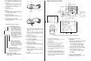
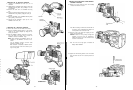
74. Video Output
Connector
(B
NC)
(VIDEO
OUT)
A
composite
vid
eo
signal is
provided
at
this
connec-
tor
- 15 -
75. Gen-lock Input
Connector
(ENC)
(GEN-LOCK)
The
colour
vi
deo
signal
of
the camera is
automatically
synchronized
to
the gen-lock
signal
(composite or
black burst)
whtch
is
supplied
to
this
connector.
The
gen-lock
signal
is
used
for
system
reference,
such
as
when
using
a
Special
Effects
Generator
Caution:
If the gen-lock
signal
is
jittery
(such
as when
obtained
from VTR p
layback),
the camera may
not be
able
to
synchronlze
properly.
76.
Multiplex
Signal
Input
Connector
(MPX)
Communications
between
the camera
side
and the
Remote
Control
Unit
(RCU) are
available
through
a
Single
coaxial
cable by
using
this
Connector
as the
composite
signal,
gen-lock
signal,
control
signal
and
Intercom/audlo
signal
are
multiplexed,
and the
com-
posite
signal
is
output
from the
Remote
Control
Unit.
(RCU)
77.
External
DC
Input
Connector
(XLR,
4-pin)
(EXT DC)
This
connector
accepts
the
power
cable from
an
external
DC
source suppying
nominal
power
of
12V.
2A
(a
belt
type battery
or
car battery for
example)
This
connector
also
accepts the
power
cable from
an
AC
adaptor. F
or
powering
the
studlo
configuration,
a
12V DC, 2,5A
power
source is required.
Cautions:
?? Use only
with
a
12V DC
power
source
with
a
Class
2
rating.
Do
not
use
with
an
external
stor-
age
battery
unless
provided
with
an
8A
rated
fuse,
located
withln
5
inches
of
the battery
con-
necting
means.
??
An
external
DC
source
supplied
to
this
connector
gets the highest
priority,
if it is
selected
before
the battery
connector
or
Multicore/VTR
DC
source
78.
Circuit
Protector (BREAKER)
When
excessive
current
flows
i
nto
the camera due
to
some
fault,
the red button of
this
cIrcuit
protector
pro-
trudes
to
cut
off
the
circult
power
After
solving
the
problem,
press
the red button
again
to
reset
the
circuit
protector.
Caution:
Refer
serving
to
qualifled
serwce
person-
nel
to
solve
the
problem.
79.
VTR/RCU
Connector
(26pin)
(VTR/RCU)
When
using
the camera together
with
a
Panasonic
portable
colour
VTR,
the
specified
VTR Cable
should
be connected
between
the camera and
VTR.
T
his
connector is
also
used
for
connection
with
the
26-pin
studio
cable from the
Remote
Control
Unit
(RCU)
for
comprehensive
system
operation.
When
connecting
the
26-pin
studio
cable t
o
this
connector,
the
camera
is automatlcally
set
to
the
Remote
Control
Unit
(RCU)
operatlon
mode
??
3/4"
U-vlsion
portable
VTR
(14-pin)
WVCA26A14
(26P-14P
cable)
MII
portable
VTR
(26-pin)
WV-CA26A26
(26P-26P
cable)