


USER
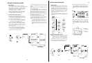
SETTING
After
setting
the
scene
File
Selection
Switch (10) of the
camera
or
(131)/(164)
of RCU
(RCB)
to
the
USER
SET
position,
the
camera
operating
condition
can be
changed
by the user
to
the
desired
condition
How to set the
User
Set
Menu
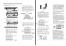
1. Set the
Scene
File
Selection Switch (10) of the camera
or
(131)/(164)
of the RCU
to
the
USER
positlon.
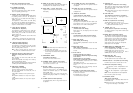
SCENE
USER
A
or
SCENE
USER
B
is
displayed in
the
viewfinder.
Notes:
1
The
selection
of
USER
A a
nd
USER
B
can be
made by
setting
the
Scene
File
Selection
Switch
User
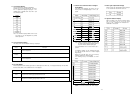
Set Menus are shown
in
the following.
** Camera
to
the
USER
pwtlon
while
pressing
the Page
Switch (13)
or
Check
Button
(25).
2. When
only
usin
g
the
Scene
File
Selection
Switch
in
the
above
procedure,
the user
file
selected
last
will be dlsplayed
2. Set the
User
Set
Switch in
the
side
cover
to
position
1.
The
User
Set
Menu is
displayed in the
viewfinder
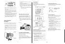
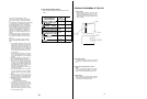
Set the
User
Set
Switch in
the
side
cover
to
position
2
The
User
Set
Menu is
also
displayed
on
the
monitor
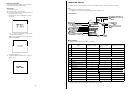
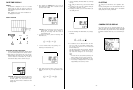
No.1 to No.8
menus
can be dlsplayed by
every
press-
ing the Page Switch and
seting
is
available
from
Camera
or
Remote
Control
Unit
side.
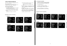
Camera
Menu Description
1. CONTRAST (LOW,
MID,
HI) (Contrast
Level
Setting)
The
Contrast
(gamma)
level
can be selected
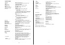
2. SHARPNESS (LOW, MID, HI)
(Sharpness
Level
Setting)
The sharpness (detail)
level
can be selected.
3.
FLESH TONE (-2
-
2) (Flesh Tone Setting)
Flesh
tone can be
adjusted
from -2
to
2
range in
5-
step
4.
CHROMA
GAIN (-2
-
2)
(Chroma
Gain Setting)
The
chroma
gain
can be selected from -2
to
2
range
i
n
5-step.
5.
PEAKING
(Operating
ratio
Adjustment)
The
ratio
of AUTO
IRIS/ELC
detected
peak
to
average
can be
adjusted in
a
range
of 9 steps
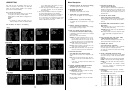
6.
AREA:
ALL,
CENTRE, TOP CUT, BOT CUT,
R/L
CUT
(Photometric
Measurement Method Setting)
A
photometric
measurement method can be selected
for AUTO
lRIS/ELC
ALL:
All
the
screen
area is
measured
CENTRE: The
screen
is
measured
mainly
in
the cen-
tre
area,
approx.
o
ne-third
each
of the top and
bottom and o
ne
third
each
of the
right
and left
parts of
the
screen
are cut
out
from
measurement.
TOP CUT:
Approx. one-third
of the top part of the
screen
is
cut
out
from
measurement
BOT CUT: Approx. o
ne-third
of the bottom part of the
screen
i
s
cut
out
from
measurement
FUL CUT: Approx o
ne-thtrd
each
of
the
right
and
left
parts of the
screen is
cut
out
from
measurement.
7.
CLEAN
DNR,
OFF/LOW/HI
(Clean
DNR (Digital
Noise
Reduction Switch)
The SIN
ratio
on
the
screen
can be
improved
by
thls
switch.
Note: When the camera is operating
alone,
this
func-
tion can be made by the DNR
Switch
inside
the
camera
In
this
case, the displayin the
menu
shows
the set
siwtch
condition
8. LIGHTING:
HALOGEN/FLUORESCENT/OUTOOOR
(Lighting Selection) (Only
Scene
2)
HALOGEN:
Thls
position is
suitable for
shooting
under
halogen
Iighting.
FLUORESCENT:
This
position
is
suitable
for
shooting
under
fluorescent
Iighting
OUTOOOR:
This position is suitable
for
shooting
9. AUTO IRIS: ADJ
ON/ADJ
OFF
(Auto Iris
Level
Fine
Adjustment)
When the mode is set
to
ADJ
ON,
fine
adjustment
of
ALC/ELC
convergence l
evel
can be made
with
the iris
VR control
on
the RCU (RCB)
if
the camera is
used
with
an
RCU
(RCB)
and the iris mode is set
to
AUTO in
the SETUP menu.
10.
SHUTTER
SW, ACTIVE,
INHIBIT
(Shutter Active
Inhibit
Selection Switch)
When the
INHIBIT
position
is selected, shutter
function
is not
avallable
even if the Shutter
On/Off
Switch is
turned
on
11.
SHUTTER
MODE,
STEP/SYNCHRO/ELC
(Shutter
Mode Setting)
STEP:
Select
this
mode
to
set the
shutter
speed
by
the Step mode
shutter
setting
SYNCHRO:
Select
this
mode
for the
fine
adjustment
of
the shutter
speed
ELC:
Select
this
mode
to
control the
electronic
shutter
speed
automatically
to
regulate the amount
of
light.
12. STEP, 1/120, 2/250
,
1/500
,
1/1000,
1/2000,
1/
4000,
1/10000
(Step Mode
Shutter
Setting)
When the Shutter Mode
Setting is
set
to
STEP, the
shutter
speed
should
be selected by
this
item
13. SYNCHRO, 50.0
-
250.4 Hz
(Synchro Mode
Shulter
Adjustment)
When the Shutter Mode
Setting
is set
to
SYNCHRO,
the shutter
speed
can be adjusted by
this
i
tem.
This
mode can
prevent
the line
noise
when
shooting
the CRT
dlsplay
14.
FLD/FRM,
FIELD/FRAME
(Field/Frame
Setting)
The FIELD
means
CCD
field
storage. The FRAME
means
frame storage,
in
which
case vertical
resolution
increases
FIELD:
Set
to
thls
mode when
shooting
moving
oblect
FRAME
1: Set
to
this
mode when
shootlng
stlll
object
FRAME 2: Set
to
this
mode
when
better
resolution is
required
Note:
It is
recommended
that FRAME is
normally
selected,
because
the
residual
ima
ge
will
increase if field is selected
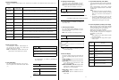
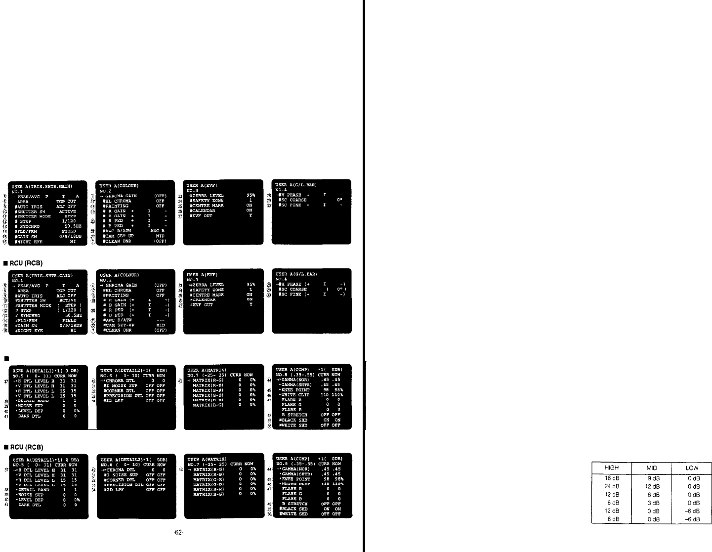
15. GAIN SW, 0/
9/18,
0/12/24, 0/3/6,
-
6/0/12,
-6/0/16dB
(Gain
Setting)
The
HIGH/MID/LOW
level
of the
High
Gain
Selection
Switch
can be set as shown
below
under
outdoor
lighting
After the
setting is
completed,
set the
User
Set
Switch
to
the OFF
position
- 63 -