


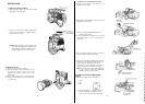

4. S
elect
the
proper
CC
filter
according
to
the
colour
temperature
at
the
scene,
using
the
Filter
Selection
Wheel
(31)
whlle
referrlng
to
the
Table
on
page
58
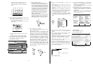
5.
Set
the
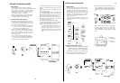
black balance as follows:
Set the Auto
White/Auto
Black Set
Switch
(6)
to
the
ABC
position
momentarily
by
pressing
it
down.
The
lens
iris
is
automatically
closed
and the black balance
is
set
automatlcally.
AWC
.
ABC
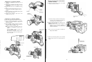
When the black balance has
been
set, the
lens
iris
returns
automatlcally
to
its
previous
position.
The Auto
Warning
Indicator
in
the
viewfinder
blinks
while
the
black balance
is
being
set and it goes off when the
black balance has
been
correctly set.
While
the black
balance
is
being
set, ABC
also
blinks
in
the
wewflnder
screen,
and ABC OK appears when the
setting
is
completed.
After
a
few seconds, ABC OK
disappears
from the
screen.
If
the Auto
Warning
lndicator
remains
lit
and ABC NG appears
in
the
wewflnder
screen,
the black balance adjustment should be
car-
ried
out
once more.
Refer to ‘Setting the Black
Balance’
on
page 56 for
details
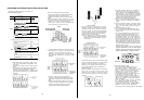
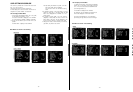
6. Set the
whlte
balance as follows.
Set the
White
Balance
Selectlon
Switch
(28)
to
either
A
or
B
positlon
(stored
in
appropiate
memory).
While
aiming
the camera at
a
white
object,
e.g. gray
scale
chart
or
white
paper, set the Auto
White/Auto
Black
Set
Switch
(6)
to
the AWC
position
momentarily
by
pressing
it
up.
Pay
attention
so that the light
source
or
reflected
llght
from
metallic
objects
does
not come
in
the
view
The
whlte
balance
is
automatically set
MANUAL
AWC
A
ABC
When the
white
balance has
been
set, the
blinking
Auto
Warning
Indicator
in
the
viewfinder
goes
out
and
the
blinking
AWC A
or
AWC
B
in
the view
finder
screen
turns
into
AWC A OK
or
AWC B OK,
respectively.
If
the Auto
Warnlng
Indicator
remains
lit
and AWC A
NG
or
AWC B NG appears
in
the vi
ewfinder
screen,
This
the
white
balance adjustment should be
carried
out
indication
disappears
after
a
few seconds.
once more.
However,
before
proceeding
with
the
adjustment, make
sure
the
Filter
Selectlon
Wheel (31)
is
set correctly
Refer
to
'Setting
the
Whlte
Balance’
on
page 57 for
details
- 46 -
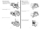
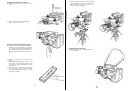
7.
Confirm
the
flange-back
adjustment of the
lens.
If
it
is
not correctly set,
readjust
the
flange-back
8. Adjust
the
audlo
level
of the
mlcrophone.
Tum the
Audlo
Input
Level
Control (24)
on
the Camera
Head to
clockwise
for
increasing
the
audio
level.
9.
Confirm
the
audio
level
on
the
level
meter of the
VTR
or
in
the
viewfinder
10.
If
the
electronic
shutter
operatlon
is
desired,
turn
on
the
Electronic
Shutter
On/Off
Switch
(11)
to
select
the
appropriate
shutter
speed
11.
The
camera’s
condition
may be
confirmed
by
pressing
the
Check
Button
(25)
while
a
normal picture
is
being
vlewed.
Refer
to
‘Character
Dlsplay’
on
page 67 for
details.
12.
Aim
the camera at the
scene
to
be
recorded
and
adjust
the
focus
and
zoom
of the
lens
accordingly
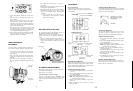
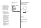
13. P
ress
the VTR
Start/Stop
Button (92)
on
the
lens
or
(5)
on
the camera. The
Recording/Tally
Indicator
in
the
viewflnder,
the
Tally
Light
(101)
on
the
front
of the
viewfinder
l
ight
and the
Top
Tally
lights
while
record-
ing
is
in
progress
/ Stop
Button
.
REC
AUDIO
TALLY
. AUTO
14.
Press
the VTR
Start/Stop
Button
to
stop
recording
when
this
is
desired.
The
Recording/Tally
Indicator
15 After
recording,
you
may
review
the
picture
in
the
and the
Tally
Llght
and Top
Tally
go out.
viewfinder
To
resume
recording,
simply
press
the VTR
Start/Stop
Button
again
1
Press
the VTR
Start/Stop
Button and reverse the
cassette tape
2 Set the VTR
in
the
Play
mode and
press
the
Return
Video
Button (90)
on
the
lens
OPERATING
PROCEDURE FOR ENG/EFP APPLICATION
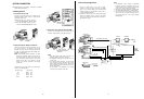
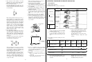
1.
ENG
Application
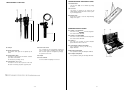
(1)
Make
all
required
connections.
(2)
Remove
the
Lens
Cap
(3)
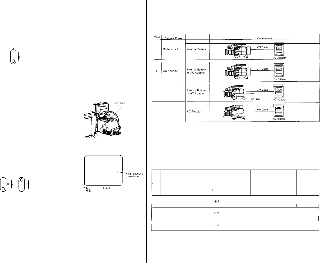
Select
the
power
source
according
to the
table
below
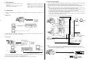
3
External
DC
4
Supplled from
VTR
Notes:
Portable VTR
POWer
3
In case 4. the
AC
Adaptor should
have
sufflclent
capaclty
to
power
both
the
camera and the VTR.
4 The
power
of camera
is
turned
on/off
automatlcal-
ly
by the
power
supply
connector
The arder of
prtorlty
for the
power
supply
connec-
tors
is
as follows:
4-pin
DC
Connector
>
Battery
Jack
>
26-pin
Connector
1
In case 4, the
optional
VTR Cable
WV-CA26A26,
WV-CA26A14
should be
used
2.
It
is
not
recommended to
supply
camera
power
from the
built-in
battery
in
the
portable
VTR
since
recording
tlme
would
be
much
too
short
in
this
case
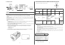
(4)
Set the
swltches
of the camera
according
to the VTR
it
is
connected
to
Case
VTR
Audlo
Level
Earphone
VTR
Video
VTR Vldeo
NO.
Portable
VTR
Used
Compatlblllty Selection
Selection
output
output
Switch
(58) Switch
(55)
Switch
(56)
Selection
Selection
Switch 2 (59)
Swltch
1 (57)
1
1/2"
or
3/4"
portable
VTR
with
10-pin
camera
connector
(Note 2)
-20
dB
INT
R/G/B
ENC
|
|
|
|
|
2
3/4"
portable
VTR
with
14-pin
camera
connector
-60 dB
PB
R/G/B
ENC
|
3
1/2"
portable S-VHS VTR with
14-pin
camera
connector
-20
dB
PB
Y/C/B SELECT 2
|
| |
|
|
|
|
4
MII
portable
VTR
with
26-pin
camera
connector
/
-60 dB
PB
Y/P
R/P
B
SELECT 2
|
|
|
Notes:
1
If the VTR Video Output
Selectton
Swltch
1
or
2
is
not set
to
the
correct
position,
picture
recording
is
not
possible
|
| |
|
2 If the
VTR
is
from
a
manufacturer
other
than
Panasonic
and
it
pauses
whlle
it
should be
recording,
and
vice
versa, set the VTR
Compatlbllity
Switch
(58)
to
the
positlon
1
- 47 -