


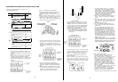
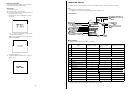
Display
Position
of
High
Light
Chroma
Switch
HL CHROMA
OFF
HL CHROMA
ON
(LOW position
had
been
set in
the
No 2
HL CHROMA
ON
(HIGH
position
had
been
set in
the
No
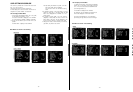
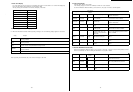
3. Shutter
Speed
Display
0ne
of the
following
displays appears
for
o
ne
second when the
position
of the
Electronic
Shutter
On/Off
Switch (ll) is
changed
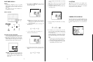
Display
Shutter/High Gain
Indicator
(LED)
Description
SHUTTER OFF
SHUTTER 1/120
SHUTTER 1/1250
OFF
ON
ON
The
Electronic
Shutter
On/Off
Swtich is set t
o
OFF. Normal camera
operation.
Camera is set to electronic shutter mode with shutter speed of 1/120 seconds.
Camera is set
to
electronic
shutter mode with shutter speed of 1/250 seconds
SHUTTER
1/500 ON
SHUTTER
1/1000
ON
SHUTTER
1/2000
ON
Camera is set to
electronic
shutter
mode
wih
shutter
speed
of 1/500 seconds
Camera is set to
electronic
shutter mode
wih
shutter speed of 1/1000 seconds
Camera is set
to
electronic
shutter mode with shutter speed of 1/2000 seconds
SHUTTER
1/4000
ON
SHUTTER 1/10000 O
N
SYNCHRO
SCAN
ON
Camera is set to electronic shutter
mode
wih
shutter speed of 1/4000 seconds
Camera is set to
electronic
Shutter
mode
with shutter
speed
of 1/10000 seconds
Camera is set to the Synchro Scan mode
ELC
ON
The
Electronic
Light
Control is
being
activated
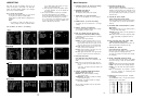
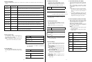
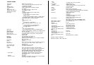
4.
Detail
Correction
State
The
detail/aperture
correctilon
state is
displayed
for
one
second when the
setting
of
the Detail
Level
Position
of the Detail
Level
Selection
Switch
Display
(20)
Selection Switch (20) is changed
Note: The
detail/aperture
correction
state is
also
dis- DETAIL OFF OFF
played when the Check Button (25) is pressed.
DETAIL LOW LOW
5.
Clean
DNR Display
The
clean
DNR
state is
displayed
for
o
ne
second
when the
position
of
the
Clean
DNA Selection Switch Display
(17) CLEAN DNR OFF
- 70 -
DETAIL HIGH
HIGH
The
above
displays
are
Indicated
by
previewing
the
Check Button (25)
Position of
the
Clean
DNR Selection Switch
CLEAN
DNR
LOW
LOW
CLEAN
DNR
HIGH
HIGH
6. High-light
Chroma
Display
The
high-light
chroma
state
is
displayed
for o
ne
sec-
ond when the
High
Light
Chroma
Switch is pressed.
Note: When the
Remote
Control
Unit is
used,
the OFF,
LOW
or
HIGH can be
selected
on
the
menu.
2
The
above
displays
are ind
icated
by
pressing
the
Check Button (25)
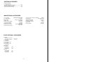
7. | Noise Suppress Display
The
I
Noise
Suppress
state
is displayed for one
sec-
ond when the item
Noise
Suppress
Switch is pressed
in the
menu
off mode
Note:
These
selections
can be made
by
the
menu
Display
Positlon of Item /
Noise
Suppress Switch
1
NOISE SUP
OFF
OFF
Note: The
above
displays are in
dicated
by
pressing
the Check Button (25)
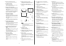
6.
Scene
File
Display
The
scene
file
setting
is changed
or
Check Button (25)
is pressed, the
followig
display
appears for o
ne
sec-
ond
SCENE
1 STUDIO:
Scene
File
Selection Switch had
been
set
to
SCENE
1
SCENE
2 ENG:
Scene
File
Selection
Switch
had
been
set
to
SCENE
2 and LIGHTING in No 1
Main
Menu
is set
to
HALOGEN
SCENE
3 OUTDOOR:
Scene
File
Selection Switch
had
been
set
to
SCENE
2 and LIGHTING in No 1
Main
Menu
is
set to FLUORESCENT
SCENE
USER
A:
Scene
file
condition is
under
the
User
A
state
SCENE
USER
B
:
Scene
file
condition is
under
the
user
B
state
9. Accumulative Recording Time Display
White
the
Check Button
(25)
is pressed, the
accumula-
tive
recording
ti
me
is
displayed
during
ENG/EFP
oper-
ation.
When a
camera/recorder
system
utllizes
an
AU-45H,
the tape
counter is
displayed inst
ead
of
accumulative
recording
time.
Notes:
1
The
display
value is
reset
to 0 HOUR 00
MIN
00
SEC
(O:OO:OO)
by
either
the
Recording
Time
Reset
Button
(21)
on
the camera
or
the
Reset
button
on
the
VTR
2. The
maximum
recording
time
that
can be
dis-
played is
7 HOURS 59
MIN
59
SEC
(7:59:59).
If
the
recording
time
should
exceed
this
value, the
display will
start
counting
again
from 0:00:00
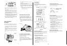
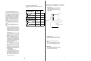
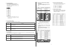
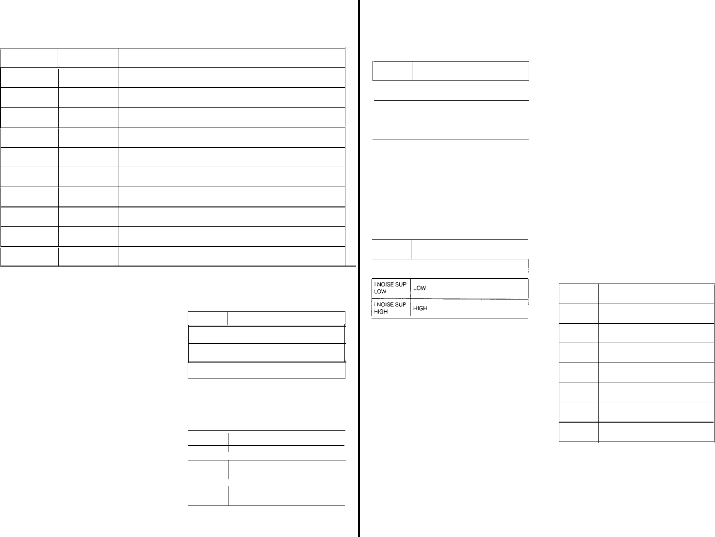
10. Switch Display/Back-up Battery
State
Display
When the
back-up
battery
for
white
balance and black
balance
memories,
as
well
as the character
display,
has
a
low
charge
‘BACK
UP NG’ is displayed
Replace
the
back-up
battery
immediately
When
pressing
the
switches
on
the front
or
side
of
the
camera, the
switch
“ame pressed ca” be dlsplayed
in
the
vlewflnder
as shown
below
Notes:
1
Refer
replacement
of
the
back-up
battery
to
quali-
fied
service
personnel
2. The
back-up
battery
will
supply
power
for
approx-
imately
10 years
Display
Description
GAIN
High
Gain Selection Switch (29) is pressed.
WHITE BAL
Whlte
Balance
Selection
Switch (28) is
pressed.
BAR/N
EYE
/
Colour
Bar/Night
Eye/Camera Selection
CAMERA
Switch (27) is pressed.
AUTO
W/B
Auto
White/Auto
Black
Set Swich
(6) is
pressed
LENS IRIS
NONE
BACK-UP
NG
Lens
lits
Selection
Switch
(7)
is
pressed
Back-up
can not be
operated
Back-up
can
not
be
operated
- 71 -