


51
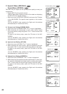
BP 2
Switch
position
BP 1 Function
Function
Switch
position
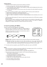
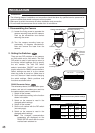
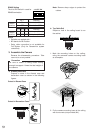
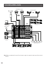
RS485 Setting
The 4-bit DIP switch in used for
RS485 termination.
ON
Marking
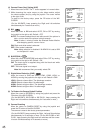
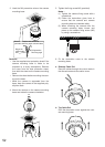
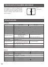
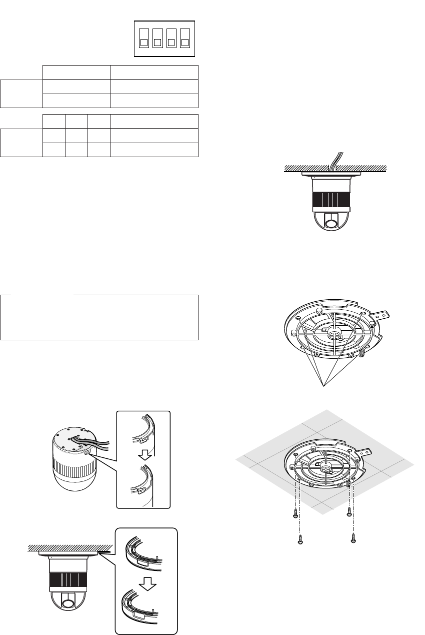
1. Mark the mounting holes on the ceiling,
using the removed camera mounting base
as a template.
2. Fix the camera mounting base to the ceiling
with four screws (not provided, M4).
Note: Remove sharp edges to protect the
cables.
3. Assemble the Camera
Reverse the disassembly procedure. Take
care not to cut any cables.
OFF
Termination ON
Termination OFF *
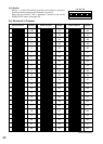
b. Top Cable Exit
Prepare a hole in the ceiling board to run
the cables.
1234
ON
4-bit DIP SW
BP 3 BP 4
ON ON ON
OFF OFF OFF
Half duplex (2 line)
Full duplex (4 line) *
Notes:
• Defaults are marked with
*.
• BP stands for Bit Position.
• Daisy chain connection is not available for
Full Duplex. (Only for Panasonic’s system
controllers)
Be sure to select a ceiling board strong
enough to support 4 times the total weight of
the camera.
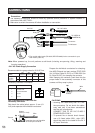
Precaution
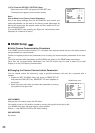
a. Sideway Cable Exit
Prepare a cutout in the diecast case and
decoration cover as shown in the following
figures.
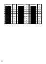
Cutout in Diecast Case
Cutout in Decoration Cover