


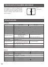
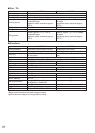
53
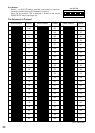
#24
(0.22mm
2
)
Copper wire size
(AWG)
Length
of cable
(approx.)
(m)
(ft)
#22
(0.33mm
2
)
#20
(0.52mm
2
)
#18
(0.83mm
2
)
20 30 45 75
65 100 160 260
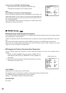
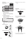
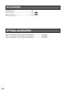
Accessory Connector Information
Pin no. Power source
1
2
3
4
24 V AC LIVE
24 V AC NEUTRAL
Ground
Not use
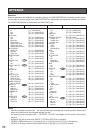
Contact
Up
Wire
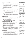
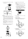
Prepare the individual conductors for clamping.
Use MOLEX band tool part number 57027-5000
(for UL-Style Cable UL1015) or 57026-5000 (for
UL-Style UL1007) for clamping the contacts.
After clamping the contacts, push them into the
proper holes in the accessory connector of this
camera until they snap in place.
• Shrinking the cable-entry seal is a one-
time procedure. Do not shrink the cable-
entry seal until it has been ascertained
that the unit is functioning.
CONNECT THIS TO 24 V AC CLASS 2
POWER SUPPLY ONLY.
• To prevent fire or electric shock hazard,
use a UL listed cable (VW-1, style 1007)
should be used for the cable for the 24 V
AC Input Terminals.
Contact
Insert
Up
A
Approx.
0.1 inch
Insert the wire until A position
and clam
p
the contacts.
Wire
Up
Wire
Contact
Up
Contact
Wire
Approx.
3 mm (0.1 inch)
Insert the wire until A position
and clamp the contacts.
1
3
2
4
• 24 V AC Power Supply Connection
Recommended wire gauge sizes for 24 V AC line.
CAUTIONS
Note: When powered up, the unit performs a self-check (including one panning, tilting, zooming and
focusing operation).
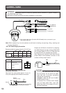
✻ The coaxial cable length (RG-59/U, BELDEN 9259) for the connection is up to
900 meters (3,000 ft.)
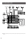
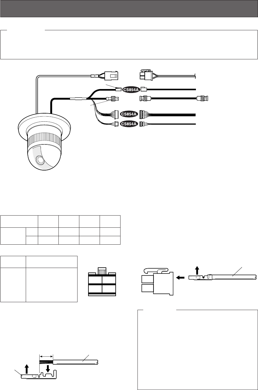
To VIDEO IN
(CAMERA IN)
Video output
24 V AC
BNC plug
Coaxial cable
RS485 cable
Data port
CONNECTIONS
BNC plug
Alarm in
Alarm out
To sensors
To indicators
• The following connections should be made by qualified service personnel or system installers in
accordance with NEC 725-51.
• Make sure to switch the camera off before installation or connection.
Precautions
24 V AC cable
How to Assemble the Cable with the
Accessory Connector
Strip back the cable jacket approx. 3 mm (0.1
inch) and separate the individual conductors.