


NETWORK PTZ CAMERA User Guide
28
NETWORK PTZ CAMERA User Guide
29
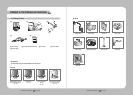
Chapter 3. Installing Camera & Network Setup
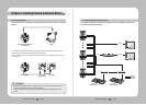
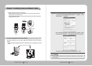
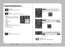
- Attaching Template & Installing STB-370NPC
Attach the enclosed template to the ceiling, then drill a hole in the ceiling according to the
88mm diameter hole marked on the template. Drop the camera cables down from the
ceiling through the hole. Next, install the base, STB-370NPC, to the ceiling as shown in the
picture.
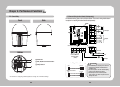
Before installing the exposed bracket, open the hinged door at the bottom of the bracket as
shown in the picture. Hold the knob on the hinged door to open it.
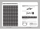
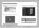
- Connect Terminal Wires
Connect the cables to the terminal block on the hinged
door.
When connecting, please refer to 2.2 Camera Wiring
Interface Board. Once the wiring is complete, close the
hinged door.
•Donotconnectthecameratoapoweroutletuntiltheinstallationiscomplete.Supplyingpower
while the installation is in progress may cause fire or damage the product.
Caution
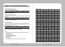
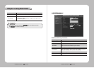
3.6. Ceiling Installation Example
Knob
Template
•Makesuretohookthecamera'ssafetycabletothemountbeforeproceeding.Otherwiseyoumaybe
exposed to serious injury caused by the camera falling.
Caution
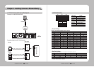
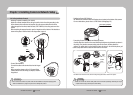
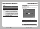
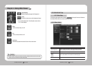
- Configuring Camera DIP Switches
DIP switches for communication and ID protocols are located on the bottom of the camera.
For more instructions, please refer to 3.2 DIP Switch Settings(Page 25).
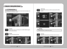
- Connecting Camera Safety Cable and Attaching Camera
Carefully attach the camera to the mount following the alignment guide marks as shown in
the picture. First, hook the camera's safety cable on the mount, and then attach the
camera. The safety cable is coiled inside the base. As shown in the left hand picture, pull
out the safety cable from the base and then hook it to the mount.
※To attach the camera to the mount, refer to the alignment guide marks as shown in the picture.
Protocol (SW1,2,3), ID(SW4,5)
Direction
Guides
Align the Direction
Guides
Safety
Cable
Direction
Guides