


NETWORK PTZ CAMERA User Guide
14
NETWORK PTZ CAMERA User Guide
15
Front Side
1
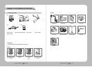
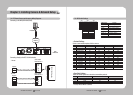
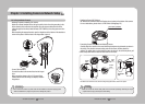
2.2. Camera Body
SW1 SW2
SW4SW5
SW3
OFF
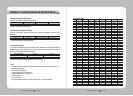
1-1Protocol
STW
Pelco-D
Pelco-P
SEC
Panasonic
Vicon
Honeywell
AD
Baud
2-12-2
3-23-3
2-3ETC
Termination
422/485
2-43-13-4
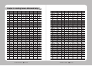
Address
Weight
1-21-31-4
OFF
OFF
OFF
OFF
OFF
OFF
OFF
OFF
OFF
ON2,400
4,800
9,600
19,200
ON
ONON
ON
ON/OFF
AUX1
AUX2
Response
ON
ON
4-1
1
2
4
8
16
32
64
128
4-2
4-3
4-4
5-1
5-2
5-3
5-4
ON
OFF
OFFOFF
OFFX
O
OFF
OFFOFF
OFF
OFF
OFF
OFF
ON
ON
ON
ON
OFF
OFF
ON
ON
OFF
OFF
ON
ON
OFF
ON
OFF
ON
OFF
ON
OFF
ON
Bottom
❶
Unlock Button
2
SW1, SW2, SW3: Communication Switch
3
SW4, SW5: ID Switch
4
Safety Cable Hook
* For instructions on configuring the switches, please refer to Page 16: 3.2 DIP Switch Settings.
2
3
4
Chapter 2. Part Names & Functions
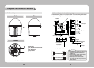
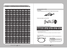
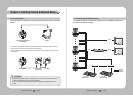
2.3. Camera Wiring Interface Board (Sold Separately)
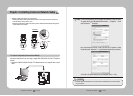
· RS485 Communications
· RS422 Communications
Camera
Camera
D+
D-
D+
D-
TX+
TX-
TXD+
TXD-
TXD+
TXD-
RXD+
RXD-
Controller
Controller
Control Signal Connection
For the camera wiring, please refer to the picture below. The camera’s wiring interface board
is equipped in a housing and bracket that are sold separately.
•Themaximumpowercapacityofthealarmand
AUXoutputsis30VDC/2A,125VAC/0.5A,and
250VAC/0.25A.
•Toconnectproductsoverthecamera’scapacity,
please use an additional relay device.
•ConnectingthepowerconnectorandGND
incorrectly to the NC/NO and COM ports can
cause a short circuit which may lead to fire and
damage the camera.
Caution
Communications and AUX
D+ D- TX+ TX- GND
A_COM A_NO
Refer to Control Signal
Connection Diagram
(Below)
Power Supply
AC24V 2.5A
Alarm
ETHERNET
Audio IN/OUT
Alarm Output
Alarm Input
Power Input
AUX Output
Ground
Video OutputVideo Output